EasyManua.ls Logo

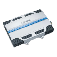
Infinity 7541A User Manual

Infinity 7541A
8 pages
To Next Page IconTo Next Page
Page #1 background imageLoading...
Page #1 background image
Thank you
for purchasing a Reference Series amplifier.
In order that we may better serve you should you require warranty
service for your new amplifier, please retain your original purchase
receipt and read the enclosed warranty information card.
reference series
311a,611a,
1211a,7521a,
7541a,5761a
instructions

Other manuals for Infinity 7541A

Questions and Answers:

Infinity 7541A Specifications

General IconGeneral
BrandInfinity
Model7541A
CategoryAmplifier
LanguageEnglish

Summary

Infinity Reference Series Amplifier Instructions

Introduction and General Warnings

Introduction to Reference Series Amplifiers

Brief overview of the Reference Series amplifiers and thank you message.

Important Safety Warning: Hearing and Property

Warns about potential hearing damage and property damage from loud music.

Recommendation for Professional Installation

Strongly advises professional installation for optimal performance and safety.

Installation Warnings and Tips

Wear Protective Eyewear During Installation

Mandatory safety practice to wear protective eyewear when using tools.

Pre-Installation Safety Steps

Steps include turning off the system and disconnecting the battery.

Check Mounting Surface Clearances

Verify sufficient space and check for hidden obstacles before drilling.

Caution with Vehicle Lines and Wiring

Exercise extreme caution when drilling near fuel, brake, vacuum lines, or wiring.

Prepare for Drilling and Cutting Operations

Use a utility knife to clear fabric/vinyl to prevent snagging during drilling.

Proper Cable Routing and Separation

Keep signal cables separate from power and speaker wires to avoid interference.

Ensure Secure and Insulated Connections

All electrical connections must be secure and properly insulated.

Correct Fuse Replacement Procedure

Only use fuses of the same type and rating as the original.

Choosing a Location and Mounting the Amplifier

Selecting an Optimal Mounting Location

Mount in trunk/cargo area, avoid shifting cargo, ensure adequate ventilation.

Under-Seat Mounting Precautions

Ensure clearance from seat mechanisms and passenger feet; mount securely.

Protect Amplifier from Moisture

Mount amplifier in a dry environment; never outdoors or in the engine bay.

Power Connections and Wiring

Ground Connection Best Practices

Connect to a solid chassis point, remove paint, and use a lock washer.

Battery Power Connection Setup

Connect to positive battery terminal, install fuse holder near battery, route wire safely.

Remote Turn-On Connection

Connect to source unit's remote output or vehicle accessory circuit.

Wire Gauge Chart for Power Connections

Chart specifying minimum wire gauge based on amplifier model and wire run length.

Speaker Connection Wire Gauge

Use a minimum of 16-gauge wire for all speaker connections.

High-Level Input Connectivity

Explains use of speaker-level inputs for head units without RCA outputs.

Amplifier Application Diagrams (311a, 611a, 1211a)

311a, 611a, 1211a Application Overview

Single-channel amplifiers with dual terminals for multiple woofer setups.

Minimum Speaker Load for 311a/611a/1211a

The minimum permissible speaker impedance is 2 ohms.

Amplifier Application Diagrams (7521a)

7521a Stereo and Bridged-Mono Operation

Configurable for stereo or bridged-mono operation for flexible system design.

7521a Speaker Impedance Requirements

Minimum impedance: 2 ohms stereo, 4 ohms bridged.

Amplifier Application Diagrams (7541a)

7541a Application Modes

Supports 4-channel stereo, 3-channel, or 2-channel bridged operation.

7541a Speaker Impedance Requirements

Minimum impedance: 2 ohms stereo, 4 ohms bridged.

7541a Bass Boost Feature

The Bass Boost control only influences the rear channels.

Amplifier Application Diagrams (5761a)

5761a Configuration Options

Supports 6-channel, 5-channel, or 3-channel configurations.

Input Mode Switch Explained

Explains INT (internal) and EXT (external) modes for subwoofer signal routing.

5761a Speaker Impedance Requirements

Minimum impedance: 2 ohms stereo, 4 ohms bridged.

Installation and Setup Controls

Setting the Crossover Frequency

Guide to setting crossover modes (FLAT, HP, LP) and frequency for optimal sound.

Understanding Mode Switch Settings

Explanation of FLAT, HP, and LP mode functions for speaker signal routing.

Setting Input Sensitivity

Step-by-step guide to setting input sensitivity to minimize distortion and maximize output.

Optional Remote Level Control

Information on connecting and installing the optional remote level control (100rc).

Setting the Bass Boost

Details on using the bass boost control to enhance bass output at 50Hz.

Auxiliary Output Function

Explanation of full-range AUX outputs for connecting additional amplifiers.

Installation and Setup Continued

Setting the Dynamic Bass Optimizer (DBO)

Guide to using DBO for low-frequency enhancement, adjusting frequency and boost level.

Understanding Status LEDs

Explanation of Clip, Power, and Protection LED indicators and their meanings.

Troubleshooting Common Issues

Covers common problems like no audio, distorted audio, and protection mode issues.

Specifications

311a Specifications

Detailed technical specifications for the 311a amplifier model.

611a Specifications

Detailed technical specifications for the 611a amplifier model.

1211a Specifications

Detailed technical specifications for the 1211a amplifier model.

7521a Specifications

Detailed technical specifications for the 7521a amplifier model.

7541a Specifications

Detailed technical specifications for the 7541a amplifier model.

5761a Specifications

Detailed technical specifications for the 5761a amplifier model.

Declaration of Conformity

Declaration of product compliance with technical standards EN 55013 and EN 55020.

Related product manuals