ERS Series Installation/Owner’s Manual
5
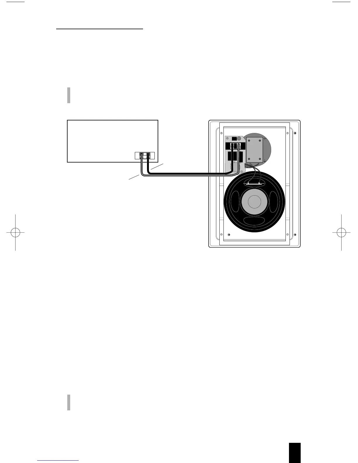
4. Strip the ends of the speaker wires about
3
⁄8". Twist the wire
strands together for terminal insertion. Connect the speaker
wires to the appropriate speaker terminals on each speaker, as
shown in Figure 3.
IMPORTANT: Make sure you observe the polarity codes (i.e.,
red is + and black is –).
Figure 3. Example of correct wiring connections used on the ERS 840.
Other models are wired similarly.
5. Before mounting the speakers, make sure the attached
mounting frame is in the extended position (see Figure 2 on
page 4). For each speaker, insert the bottom of the mounting
frame (and cable) into its respective cavity. Insert the top of the
mounting frame into the opening and slide the baffle up to fit
the cutout. Equally tighten each of the four Phillips screws
(already inserted) to sandwich the mounting frame against the
wallboard, as shown in Figure 4 on page 6.
CAUTION: DO NOT OVERTIGHTEN SCREWS! Doing so may
damage the assembly.