EasyManua.ls Logo

Ingersoll-Rand DE Series - User Manual

Ingersoll-Rand DE Series
7 pages
Print Icon
To Next Page IconTo Next Page
Loading...
Ingersoll–Rand Company 1999
Printed in U.S.A.
03540333
Form 7144
Edition 3
August, 1999
INSTRUCTIONS
for
SERIES DE ELECTRIC TORQUE CONTROL
WRENCHES/NUTRUNNERS
Series DE Wrenches/Nutrunners are designed for assembly applications requiring
precise torque monitoring and control, accuracy, consistency and repeatbility.
Ingersoll–Rand is not responsible for customer modification of tools for applications
on which Ingersoll–Rand was not consulted.
IMPORTANT SAFETY INFORMATION ENCLOSED.
READ ALL THESE INSTRUCTIONS BEFORE PLACING TOOL IN SERVICE OR
OPERATING THIS TOOL AND SAVE THESE INSTRUCTIONS.
IT IS THE RESPONSIBILITY OF THE EMPLOYER TO PLACE THE INFORMATION
IN THIS MANUAL INTO THE HANDS OF THE OPERATOR.
FAILURE TO OBSERVE THE FOLLOWING WARNINGS COULD RESULT IN INJURY.
Disconnect the Power Cord from the receptacle before performing any maintenance on this tool.
This symbol is to alert the user and service personnel to the presence of
uninsulated dangerous voltage that will cause a risk of electric shock.
This symbol is to alert the user and service personnel to the presence of important
operating instructions that must be read and understood to prevent personal injury,
electrical shock or damage to the equipment.
WHEN USING ELECTRIC TOOLS, BASIC SAFETY PRECAUTIONS SHOULD
ALWAYS BE FOLLOWED TO REDUCE THE RISK OF FIRE, ELECTRIC SHOCK
AND PERSONAL INJURY, INCLUDING THE FOLLOWING.
PLACING TOOL IN SERVICE
Use only with Ingersoll–Rand Series Controllers.
Always operate, inspect and maintain this tool in
accordance with all regulations (local, state, federal
and country), that may apply to hand held/hand
operated electric tools.
Inspect tool cords periodically and if damaged, have
them repaired by an authorized service facility.
Do not remove any labels. Replace any damaged
label.
USING THE TOOL
Always wear eye protection when operating or
performing maintenance on this tool.
Always wear hearing protection when operating
this tool.
Power tools can vibrate in use. Vibration, repetitive
motions, or uncomfortable positions may be
harmful to your hands and arms. Stop using any
tool if discomfort, tingling feeling or pain occurs.
Seek medical advice before resuming use.
Guard Against Electric Shock. Prevent body contact
with earthed or grounded surfaces. For example;
pipes, radiators, ranges, refrigerator enclosures.
Don’t abuse Cord. Never carry tool by cord or yank
it to disconnect from receptacle. Keep cord from heat,
oil, and sharp edges.
Keep work area clean. Cluttered areas and benches
invite injuries.
(Continued on page 1–2)
The use of other than genuine Ingersoll–Rand replacement parts may result in personal injury, decreased tool
performance and increased maintenance, and may invalidate all warranties.
Have your tool repaired by a qualified person. This electric tool is in accordance with the relevant safety requirements.
Repairs should only be carried out by qualified persons using original spare parts, otherwise this may result in
considerable danger to the user.
Repairs should be made only by authorized, trained personnel. Consult your nearest Ingersoll–Rand Authorized
Servicenter.
Question and Answer IconNeed help?

Do you have a question about the Ingersoll-Rand DE Series and is the answer not in the manual?

Summary

Placing Tool in Service

Using the Tool

Warning Label Identification

Grip Adjustment Procedures

Tool Lubrication and Maintenance

Gearing Lubrication

Details on lubricating the gearing assembly based on cycles or time.

Angle Attachment Lubrication

Instructions for lubricating the angle housing assembly.

Crow Foot Attachment Lubrication

Lubrication guidelines for crow foot attachments with different gear stages.

Tube Nut Attachment Lubrication

Lubrication instructions for tube nut attachments based on gear stages.

Available Resources and Ergonomics

Manual and Video Availability

Information on obtaining manuals and videos for torque tension and ergonomics.

Ergonomic Information and Posters

Details on ergonomic design benefits and related informational materials.

Overview

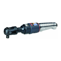
This manual describes the Series DE Electric Torque Control Wrenches/Nutrunners, designed for assembly applications that demand precise torque monitoring and control, accuracy, consistency, and repeatability. These tools are specifically engineered for professional use where exact torque application is critical.

Function Description:

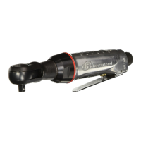
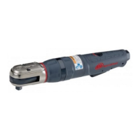
The Series DE Electric Torque Control Wrenches/Nutrunners are electric tools used for tightening fasteners to a specified torque. They are designed to provide consistent and repeatable torque output, which is essential in assembly processes where precise fastening is required. The tools are intended for use with Ingersoll-Rand Series Controllers, ensuring compatibility and optimal performance. They feature various attachments such as Angle, Crow Foot, and Tube Nut attachments, allowing for versatility across different applications and access to fasteners in various configurations. The tools incorporate mechanisms for direction switching, enabling both forward (clockwise) and reverse (counterclockwise) rotation, which is indicated by molded circular arrows on the housing.

Usage Features:

Before placing the tool in service or operating it, users must read and understand all instructions provided in the manual. It is the employer's responsibility to ensure that operators have access to and comprehend this safety information.

  • Safety First: Operators must always wear eye protection and hearing protection when operating or performing maintenance on the tool. The power cord should be disconnected from the receptacle before any maintenance is performed. A warning symbol indicates the presence of uninsulated dangerous voltage, posing a risk of electric shock. Another symbol highlights important operating instructions that must be read to prevent personal injury, electrical shock, or equipment damage.
  • Work Environment: The tool should be used in a well-lighted work area, free from explosive or flammable atmospheres. Bystanders and children should be kept away, and unauthorized personnel should not operate or touch the tool or cord.
  • Proper Tool Handling: The tool should not be forced; it is designed to perform specific tasks efficiently and safely. Users should always use the right tool for the job and avoid using it for unintended purposes.
  • Personal Attire: Operators should dress properly, avoiding loose clothing or jewelry that could get caught in moving parts. Rubber gloves and non-skid footwear are recommended for outdoor work, and protective hair covering should be used to contain long hair.
  • Workpiece Security: Workpieces should be secured using clamps or a vise, as operators often need both hands to perform job functions.
  • Body Posture: Operators should maintain proper footing, balance, and a firm grip on the tool at all times, avoiding overreaching. A warning emphasizes keeping body stance balanced and firm, and not overreaching.
  • Tool Storage: When not in use, tools should be stored in a dry, high, or locked-up place, out of reach of children.
  • Cord Management: The power cord should not be abused; never carry the tool by the cord or yank it to disconnect from the receptacle. The cord should be kept away from heat, oil, and sharp edges. Damaged, frayed, or deteriorated power cords should not be used.
  • Work Area Cleanliness: Work areas should be kept clean to prevent injuries.
  • Pre-Operation Checks: Before turning on the tool, operators should form a habit of checking to ensure that keys and adjusting wrenches are removed from the tool. The tool should not be carried with a finger on the switch to prevent unintentional starting.
  • Tool Condition: The tool should not be dropped or abused. Before further use, any damaged guard or part should be carefully checked to ensure it operates properly and performs its intended function. This includes checking for alignment of moving parts, binding, breakage, mounting, and any other conditions affecting operation.
  • Power Control: Whenever the tool is not in use, the Power Switch should be positioned to "OFF," and the power cord unplugged.
  • Alertness: Operators should stay alert, watch what they are doing, and use common sense. The tool should not be operated when tired.
  • Vibration Awareness: Power tools can vibrate in use. Vibration, repetitive motions, or uncomfortable positions may be harmful to hands and arms. Users should stop using the tool if discomfort, tingling, or pain occurs and seek medical advice before resuming use.
  • Electric Shock Prevention: Body contact with earthed or grounded surfaces (e.g., pipes, radiators, ranges, refrigerator enclosures) should be prevented to guard against electric shock.
  • Throttle Lever Position: When the Angle Head is installed or repositioned, the Throttle Lever must be positioned so that reaction torque will not tend to retain the throttle in the "ON" position.
  • Output Device Installation/Removal: When installing or removing the output device, users must always grasp a metal component of the tool (e.g., hex on the Gear Case, Tool Hanger, Torque Reaction Arm, or any metal Mounting Plate) while tightening or loosening the Coupling Nut or Spindle Cap. The composite tool body or handle should never be grasped in vise jaws to restrain the torque, as this can damage the tool.
  • Power Unit Compatibility: Power units and gear trains that exceed the capability of the output device should not be used.
  • Tube Nut Attachment Safety: The Tube Nut Attachment has an opening on the front side for construction and application purposes. Fingers should never be placed in this opening.
  • Torque Reaction Bar: The Torque Reaction Bar must be positioned against a positive stop. It should not be used as a dead handle, and precautions must be taken to ensure the operator's hand cannot be pinched between the Bar and a solid object.
  • Heat Awareness: When operated continuously for long periods, Series D Nutrunners may become hot at the spindle end. All necessary precautions should be taken to avoid skin contact with hot surfaces to prevent burns.
  • Direction Switching: Rotational arrows molded into the housing near the reversing mechanism indicate direction. Positioning the switching device nearest the circular arrow with an "F" (Forward) in the center results in clockwise rotation, while positioning it nearest the "R" (Reverse) results in counterclockwise rotation.
  • Socket Compatibility: Only impact sockets and accessories should be used; hand (chrome) sockets or accessories are not suitable.
  • Grip Adjustment: The tool features an Adjustable Grip on the hand-held housings, allowing operators to select one of three handle thickness positions. This enables individual operators to choose the most comfortable grip size based on their hand size. To adjust the grip, the power supply must be disconnected. The Adjustable Grip Latch (B) is grasped and spread slightly to raise it to the uppermost position. The Adjustable Grip (A) is then slid rearward until it stops. The grip is raised or lowered until the desired grooves inside the grip align with the appropriate lugs on the handle. Finally, the grip is slid forward onto the handle until it butts against the large portion of the handle, and the Grip Latch is pushed downward to its original position to lock the adjustment.

Maintenance Features:

Regular maintenance is crucial for maximum performance, durability, and safety.

  • Tool Maintenance: Tools should be kept clean for better and safer performance. Instructions for lubricating and changing accessories should be followed.
  • Cord Inspection: Tool cords and extension cords should be inspected periodically. If damaged, they must be repaired by an authorized service facility or replaced. Handles should be kept dry, clean, and free from oil and grease.
  • Defective Parts: Defective switches must be replaced by an authorized service center. The tool should not be used if the switch does not turn it on and off. Any damaged guard or part should be properly repaired or replaced by an authorized service center unless otherwise indicated in the manual.
  • Labels: Labels should not be removed, and any damaged labels must be replaced.
  • Lubrication: Adequate lubrication is imperative for the gearing's performance and durability.
    • Gearing: After every 50,000 cycles or one month of operation, 3 to 4 cc of Ingersoll-Rand No. 67 Grease should be injected into the Grease Fitting in the Gear Case Assembly.
    • Angle Attachment: After every eight hours of operation, 1 to 2 cc of Ingersoll-Rand No. 67 Grease should be injected into the Grease Fitting in the Angle Housing Assembly.
    • Crow Foot Attachment: Excessive lubrication can lead to attachment malfunctions. After every thirty hours of operation (or as experience indicates), 1/2 cc of Ingersoll-Rand No. 90 Grease should be injected into the Grease Fitting of the Crow Foot Attachment with two gear stages, and 1 cc for attachments with more than two gear stages. After every eight hours of operation (or as experience indicates), 1 to 2 cc of Ingersoll-Rand No. 67 Grease should be injected into the Grease Fitting of the Angle Housing Assembly.
    • Tube Nut Attachment: Excessive lubrication can lead to attachment malfunctions. After every thirty hours of operation (or as experience indicates), 1/2 cc of Ingersoll-Rand No. 90 Grease should be injected into the Grease Fitting of the Tube Nut Attachment with two gear stages, and 1 cc for attachments with more than two gear stages. After every eight hours of operation (or as experience indicates), 1 to 2 cc of Ingersoll-Rand No. 67 Grease should be injected into the Grease Fitting of the Angle Housing Assembly.
  • Repairs: Repairs should only be carried out by qualified persons using original spare parts to avoid considerable danger to the user. Only authorized, trained personnel should perform repairs. Users should consult their nearest Ingersoll-Rand Authorized Servicenter for repairs. The use of non-genuine Ingersoll-Rand replacement parts may result in personal injury, decreased tool performance, increased maintenance, and may invalidate all warranties.

The manual also provides information on available manuals, videos, and posters related to "Torque Tension and Tools" and "Ergonomics: Design for a Better Workplace," emphasizing the ergonomic features of the Series DEA Torque Control Angle Wrenches and their benefits in the workplace.

Ingersoll-Rand DE Series Specifications

General IconGeneral
ModelDE Series
TypeDie Grinder
Air Pressure90 psi
Power SourcePneumatic
Collet Size1/4 inch
Air Inlet Size1/4 inch NPT
Air Consumption4 CFM
Weight1.2 lbs

Related product manuals