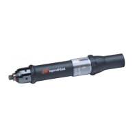
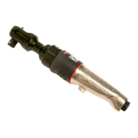
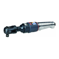
This manual provides maintenance information for Air Pulse Tools, specifically models QS110P4, QS120P4, QS140P4, and QS150P6. It is identified by document number 47156310, Edition 2, and was published in December 2012. The manual emphasizes the importance of safety, instructing users to always wear eye protection when operating or performing maintenance and to turn off the air supply and disconnect the hose before any adjustments or maintenance.
The core function of these tools, as implied by the "Air Pulse Tools" designation, is to deliver pulsed torque for fastening applications. This pulsing action typically involves an impulse mechanism that uses fluid to transmit force, providing controlled and consistent torque output. The maintenance procedures detailed in the manual primarily focus on this impulse mechanism, which is critical for the tool's performance.
Maintenance Features:
The manual provides comprehensive instructions for maintaining the tool, with a strong emphasis on the impulse mechanism. Key maintenance procedures include:
-
Changing the Pulse Mechanism Fluid: This is a detailed, multi-step process. It involves removing the hammer case and motor case assembly, accessing the mechanism, unscrewing an oil plug, and rotating a torque adjustment screw to purge the old fluid. The mechanism is then refilled with new fluid using a syringe from a Fluid Replacement Kit (Part No. EQ106S-K400). A critical warning is issued: "DO NOT SUBSTITUTE ANY OTHER FLUID. Failure to use the impulse mechanism fluid provided could damage the tool, increase maintenance and decrease performance. Use only clean fluid in these tools." After refilling, the mechanism is submerged in fluid, and the drive shaft is rotated to purge any remaining air. The process concludes with reassembly and testing the tool for torque at maximum, minimum, and mid-range settings, referring to Manual 47156203 for specific adjustment procedures.
-
Disassembly and Assembly Instructions: The manual provides detailed, step-by-step instructions for disassembling and assembling various components of the tool. These sections are crucial for repair and replacement of damaged parts.
- General Disassembly Instructions: Users are advised not to disassemble the tool further than necessary, to use leather-covered or copper-covered vise jaws to protect parts, and not to remove press-fit parts unless absolutely necessary for repair.
- Removal of Hammer Case: This involves using a jig and an adjustable wrench to unscrew the motor housing assembly from the hammer case, noting a left-handed thread.
- Disassembly of the Impulse Mechanism: This section details removing the oil plug, purging fluid, and disassembling components like the liner cap, drive shaft, and other internal parts. It references Manual 47155908 for further component disassembly.
- Disassembly of Main Shaft and Blades: Instructions are given for removing the liner upper plate, aligning and pushing out the main shaft, and then removing the main shaft, blades, and spring.
- Disassembly of Relief Valve: This involves rotating an adjust bolt, removing the liner lower plate, and pushing out the relief valve. A "NOTICE" warns against pushing the relief valve to the lower plate side to prevent the O-ring from jamming.
- Disassembly of Liner Lower Plate: This section covers removing the adjust bolt, oil plugs, liner lower plates, ball, and spring. Another "NOTICE" emphasizes careful retention of the ball and spring for future use.
- Disassembly of Sensor: Instructions for removing the sensor and its O-ring using a gimlet.
- Disassembly of the Motor Case Cover: This involves loosening bolts and removing the upper plate spacer and O-ring.
- Disassembly of Motor Case Cover Assembly: This covers removing the valve plug and shut-off valve bush after warming the valve plug.
- Disassembly of the Motor: Instructions for using a jig to disassemble the motor assembly, including removing vanes, the rotor, and the upper plate assembly.
- Disassembly of Trigger and Throttle Assembly: This involves tapping out pins, pulling out the throttle and reverse valve assembly, and separating various components like the reverse lever, throttle rod, and seals.
-
General Assembly Instructions: Similar to disassembly, general assembly guidelines emphasize using protective vise jaws, pressing on the inner ring of ball bearings when installing on a shaft, pressing on the outer ring when installing into a recess, cleaning and oiling all parts (except bearings and mechanism parts) with a thin film of oil or mechanism fluid, applying O-ring lubricant, and removing burrs.
-
Assembly Procedures: Detailed steps are provided for reassembling the various components:
- Assembly of Motor Case Cover: This involves placing O-rings, back-up rings, ball, spring, shut-off valve, and buffer plate into the shut-off valve bush. A "NOTICE" advises applying a little grease to the back-up ring to prevent misalignment. Further steps include installing O-rings and tightening the valve plug.
- Assembly of Impulse Unit: This is a critical section, detailing the reassembly of the relief valve, sensor, spring, ball, back-up ring, O-rings, adjust bolt, liner lower plates, main shaft, blades, and spring. Multiple "NOTICE" warnings are included to prevent damage to O-rings and ensure smooth rotation of components. The final steps involve tightening the adjust bolt, aligning holes, and assembling the unit with the liner upper plate and liner case, ensuring proper lubrication. Torque specifications for tightening the liner case cap are provided: 80±8Nm for QS110P4 & QS120P4, and 90±9Nm for QS140P4 & QS150P6.
- Assembly of Motor: This involves assembling the upper plate assembly to the rotor, installing vanes, cylinder pin, and O-rings, and inserting the motor assembly into the motor case.
- Motor Case Cover Assembly: Instructions for applying grease to the bearing, mounting O-rings and spacers, and installing the S-packing and motor case cover assembly.
- Assembly of Trigger and Throttle Assembly: This covers installing O-rings, hose joint assembly, throttle rod seal, throttle rod bushing, reverse valve components (spring and ball), and securing with pins. It also mentions sealing pin ends with cement to prevent air leakage.
- Assembly of Hammer Case Assembly: This involves inserting rods and springs into the rotor, assembling bearings and bushings to the hammer case, applying grease, assembling lower plate spacer with bearing and washer, aligning the washer to the hammer case groove, installing the linear case assembly, installing ST packing, and tightening the hammer case to the motor case. A "NOTICE" emphasizes matching the position of the impulse unit and hexagon position of the motor part by rotating the main shaft with fingers. The final step involves fully tightening the hammer case using Jig P, aligning the socket plug position with the bolt, to a torque of 50±5Nm.
Troubleshooting:
A troubleshooting section is included to help diagnose common issues:
- Tool rotates under no load, but not under load: This indicates the tool does not work (no pulsing). Probable causes include damaged knock pin of the liner, damaged spring for blades, pulse unit seizure, oil leaks, or a malfunction of the throttle. The solution is to immediately stop using the tool and have it repaired by an authorized Service Center.
- Tool does not stop even after throttle lever is released: This points to a malfunction of the throttle.
- Tool does not rotate under no load, but main shaft rotates if turned by fingers: Probable causes include a faulty assembled motor, too low air pressure, motor part seizure, or dust contamination. The solution is to immediately stop using the tool and have it repaired by an authorized Service Center.
- Main shaft does not rotate even if turned by fingers: Probable causes include motor part seizure, damaged vane, damaged ball bearing, seized main shaft bushing, or dust contamination. The solution is to immediately stop using the tool and have it repaired by an authorized Service Center.
Important Technical Specifications (implied):
While explicit technical specifications like RPM or weight are not provided in the excerpt, the manual does mention:
Usage Features (implied from maintenance):
- Pulse Mechanism: The tools utilize a pulse mechanism, indicating they are designed for controlled fastening with reduced reaction torque for the operator.
- Torque Adjustment: The presence of a torque adjustment screw (86) suggests that the tools allow for adjustment of their output torque.
- Modular Design: The extensive disassembly and assembly instructions indicate a modular design, allowing for individual component replacement and repair rather than requiring full tool replacement for many issues.
The manual references additional documentation for further information:
- Product Safety Information Manual 04584983
- Product Information Manual 47156203 (likely contains detailed torque adjustment procedures)
- Parts Information Manual 47155908 (likely contains exploded diagrams and part lists)
These manuals can be downloaded from www.ingersollrandproducts.com.
In summary, this manual serves as a critical guide for maintaining Ingersoll Rand Air Pulse Tools, ensuring their longevity and optimal performance through detailed, safety-conscious, and component-specific maintenance procedures. The emphasis on using the correct fluid and adhering to torque specifications highlights the precision engineering of these tools.