EasyManua.ls Logo

Ingersoll-Rand EU - User Manual

Ingersoll-Rand EU
12 pages
Print Icon
To Next Page IconTo Next Page
Loading...
Product Information
EU AND EUL AIR WINCHES
(Dwg. MHP1234)
Save These Instructions
Form MHD56383
Edition 1
November 2010
43809441
© 2010 Ingersoll-Rand Company
Question and Answer IconNeed help?

Do you have a question about the Ingersoll-Rand EU and is the answer not in the manual?

Summary

Installation

Mounting

Instructions for securely mounting the winch to a surface.

Wire Rope Selection

Details on choosing the appropriate wire rope based on load and size.

Installing Wire Rope

Step-by-step instructions for attaching wire rope to the drum.

Installation Continued

Air Supply Requirements

Information on the required air supply for optimal motor performance.

Initial Operating Checks

Essential checks before placing the winch into service.

Operation

Lubrication

Recommended Lubricants

List of recommended lubricants for Ingersoll Rand products.

Overview

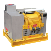
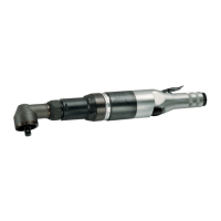
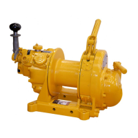
This document describes the EU and EUL Air Winches, which are industrial material handling products manufactured by Ingersoll Rand.

Function Description

The EU and EUL winches are powered by a radial piston air motor. The motor's output is transferred to the drum via a series of connected spur gears, forming a reduction assembly. Since spur gears are not inherently self-locking, a brake must be applied whenever a load is supported by the load line. These winches are designed for pulling and lifting/lowering applications, depending on the configuration and safety factors applied.

Important Technical Specifications

The winches come in two main models:

  • EU Model: 2,000 lbs (908 kg) Winch with standard drum length.
  • EUL Model: 2,000 lbs (908 kg) Winch with long drum length.

Air System:

  • Rated Operating Pressure: 90 psig (6.3 bar)
  • Consumption Volume (at rated Pressure): 65 scfm (1.8 cu.m/min)
  • Mid Drum Line Pull: 2,000 lbs (907 kgs)
  • Mid Drum Line Speed: 55 fpm (17 m/min)
  • Max Stall Pull - 1st Layer: 4,500 lbs (2,041 kgs)
  • Net Weight: 310 lbs (141 kgs)
  • Air Motor Pipe Inlet Size: 1 inch (25 mm)
  • Air System Hose Size: 3/4 inch NPT (19 mm)
  • Motor HP: 4.4

Drum Specifications:

  • Rope Anchor Hole Diameter: 9/16 inch (14 mm)
  • Drum Barrel Diameter: 6 inches (152.4 mm)
  • Drum Flange Diameter: 12.25 inches (311.2 mm)
  • Drum Length: 4-13/16 inches (97 mm)

Wire Rope Specifications (Recommended):

  • Recommended Wire Rope Size: 5/16 inch (8 mm) to 7/16 inch (11 mm)
  • Drum Wire Rope Storage Capacity (80% of values shown):
    • For 5/16 inch (8 mm) rope: 357 ft (109 m)
    • For 3/8 inch (10 mm) rope: 226 ft (69 m)
    • For 7/16 inch (11 mm) rope: 133 ft (40 m)
  • Breaking Strength (Improved plow steel wire rope with independent wire rope core):
    • 5/16 inch (0.31) rope: 9,160 lbs (3,419 kg)
    • 7/16 inch (0.44) rope: 17,780 lbs (6,636 kg)
  • Recommended Safe Working Load (lbs) (based on breaking strength and safety factors):
    • Pulling (3.5:1 factor):
      • 5/16 inch rope: 2,617 lbs (1,187 kg)
      • 7/16 inch rope: 4,500 lbs (2,045 kg)
    • Lift/Lower (5.0:1 factor):
      • 5/16 inch rope: 1,832 lbs (831 kg)
      • 7/16 inch rope: 3,556 lbs (1,613 kg)
  • Wire Rope Pitch Diameter to Drum Diameter Ratio: Minimum 15:1 for pulling/hauling, 18:1 for lifting/lowering.

Usage Features

Mounting: Winches must be mounted with the longitudinal center line horizontal and the vent cap at the top vertical center. The winch will not function properly if tilted more than 10° or if the vent cap is more than 20° off top center. For vertical or inverted mounting, the motor case can be rotated to one of four positions to ensure the vent cap remains on top. Welding to any part of the winch is prohibited. The mounting surface must be flat (within 1/16 inch or 2.0 mm) and strong enough to handle the rated load plus equipment weight. Grade 8 or better self-locking mounting bolts are required, torqued to specification. A fleet angle between the sheave and winch of no more than 1-1/2° must be maintained, with the lead sheave on a center line with the drum, at least 1.6 feet (0.5 meter) from the drum for every inch (25 mm) of drum length.

Wire Rope Installation: At least 3 tight wraps of wire rope must be maintained on the drum at all times. Wire rope should not be used as a ground for welding, nor should a welding electrode be attached to the winch or wire rope. The rope should be installed to come off the drum for overwind operation (normal application). The fused end of the wire rope is fed into the anchor hole, past two anchor screws, and positioned beneath the drum surface. The first wrap must be tight and flush against the drum flange. The wire rope should be applied to the drum so it overwinds when the drum rotates clockwise (facing the drum end) or counterclockwise (facing the motor end), as indicated by an arrow on the gear case.

Controls:

  • Winch Mounted Air Throttle (Standard): A spring-loaded, full-flow air throttle control valve is mounted on the motor. Moving the handle left (counterclockwise) pays out wire rope, and moving it right (clockwise) hauls in. The handle returns to neutral/center when released.
  • Remote Full Flow Air Throttle (Optional): Allows remote control up to 15 feet (4.5 meters) from the winch.
  • Remote Pilot Pendant Throttle (Optional): Provides remote control up to 66 feet (20 meters) from the winch. Pilot pressure from the pendant activates the winch control valve, controlling motor speed and drum rotation direction.

Brakes:

  • Manual Drum Brake (Standard): Applied by rotating the brake lever clockwise, released by rotating counterclockwise. Must be kept properly adjusted to hold the required load.
  • Automatic Drum Band Brake (Optional): A spring-applied, air-released brake. Air pressure overcomes spring pressure to release the brake when the motor is operated. When the control valve is in neutral, air vents, and the spring engages the brake to prevent drum rotation. Extended exposure to corrosive atmospheres can cause the band brake lining to adhere to the drum; it is recommended to leave the brake in a released position when the winch is not in operation and in a no-load condition.

Free Spool Clutch: A jaw-type clutch connects the gearing and drum, allowing the wire rope drum to be disengaged from the motor for manual unwinding. The clutch is engaged or disengaged via a lever on the gear case cover. The lever locks when engaged to prevent disengagement. The free spool clutch feature should not be used in combination with an automatic brake due to severe injury, death, or property damage risks.

Air Supply: The air supply must be clean, free from moisture, and lubricated for optimum motor performance. An air filter, lubricator, and moisture separator are recommended. The air line lubricator, filter, and regulator should be installed as close as possible to the air inlet, with the lubricator no more than 10 ft (3 m) from the motor. Air supply lines should be purged before final connections and kept as short and straight as possible. The air line lubricator should be replenished daily with 6 to 9 drops per minute of ISO VG 32 (SAE 10W) oil. An air line strainer/filter with 20-micron filtration and a moisture trap is recommended before the lubricator.

Natural Gas Operation (Optional Feature): The winch can be run using natural gas, but motor and valve modifications are required. Natural gas will reduce motor life, and exhaust must be piped away from the winch. All fittings and connections must be tight and inspected with leak detection equipment.

Maintenance Features

Initial Winch Operating Checks: Before placing the winch into service, perform the following:

  1. Inject a small amount of light oil into the inlet connection for initial lubrication.
  2. Check and top off oil levels in the motor and gear case grease.
  3. Operate the winch in both directions without load for one to two minutes.
  4. Perform a new brake band lining run-in procedure by operating the winch without load in the payout direction while gradually applying the brake, allowing it to slip for approximately one minute. Avoid overheating the brake.
  5. Check and adjust brake operation as needed.
  6. Check limit switches, locking mechanisms, and all safety devices.
  7. Ensure foundation mounting fasteners are secure.
  8. Install the drum guard if provided.

Storage: When storing the winch, it should be in a no-load condition, wiped clean, and lubricated to prevent rust. For storage from an air source, place a small amount of 20 weight oil at the air inlet port. Mufflers and breathers should be removed and replaced with threaded plugs to prevent dust and moisture. Manual band brakes should be stored in the disengaged position.

Lubrication:

  • Air Line Lubricator: Check daily.
  • Motor Oil Level: Check weekly.
  • Gear Case Grease: Check weekly.
  • Motor Oil Change: Annually or every 1000 hours of winch operation.
  • Gearbox Grease Change: Annually or every 1000 hours of winch operation.

Recommended Lubricants:

  • Wire Rope: Ingersoll Rand Lubri-Link-Green® (16 oz) or ISO VG 100 (SAE 30W) grade oil.
  • Bearings and Gear Case: 70 1 LB grease.
  • Air Line Lubricator: 29665 (1 Qt).
  • Air Motor Oil:
    • Below 32° F (0° C): ISO VG 32 (SAE 10W)
    • 32° to 80° F (0° to 27° C): ISO VG 68 (SAE 20W)
    • Above 80° F (27° C): ISO VG 100 (SAE 30W) (Units shipped from factory with this lubricant).
    • Caution: Do not use synthetic or detergent lubricants in air motor, as they can cause oil to blow by piston rings.
  • Grease Grade:
    • -20° to 50° F (-30° to 10° C): EP 1 multipurpose lithium based grease.
    • 30° to 120° F (-1° to 49° C): EP 2 multipurpose lithium based grease (Units shipped from factory with EP 2 grease).

Motor Oil Capacity: 3 pints (1.44 litres). Oil should be level-checked daily and drained/refilled as needed, especially in freezing temperatures.

Wire Rope Maintenance: Follow the wire rope manufacturer's instructions. At a minimum, clean the wire rope with a brush or steam to remove dirt. Caution: Do not use acid-based solvents. Apply a wire rope lubricant (Ingersoll Rand Lubri-Link-Green® or ISO VG 100 (SAE 30W) grade oil) weekly or more frequently depending on service severity.

Natural Gas Lubrication:

  • Caution: Use of other than PAG Synthetic oils can cause premature seal failure, leading to motor damage. Refer to caution label part number 71470744.

Inspection: Frequent and periodic inspections are crucial. Frequent inspections are visual examinations by operators or Ingersoll Rand trained inspectors during routine operation. Periodic inspections are thorough inspections by Ingersoll Rand trained technicians. Inspection intervals depend on component criticality and usage severity. Deficiencies must be reported and corrected.

Wire Rope Reports: Maintain records of wire rope condition as part of a long-term inspection program.

Frequent Inspection (Beginning of each shift):

  1. Surrounding Area: Check for oil leaks and ensure no slippery surfaces or obstructions.
  2. Hoses and Fittings: Inspect for damage, air leaks, and loose connections.
  3. Muffler: Check for restrictions or external damage.
  4. Manual Shut-Off Valve: Test for proper operation and free movement.
  5. Guards: Verify wire rope does not contact guards and that guards are secure.
  6. Winch: Inspect housings, controls, external brake, and drum for damage; check all external bolts.
  7. Winch Operation: Power winch in both directions; it must operate smoothly without sticking, binding, or abnormal noises.
  8. Pendant (optional feature): Ensure pendant levers operate smoothly and return to neutral.
  9. Manual Throttle Lever: Ensure smooth operation and return to neutral.
  10. Wire Rope: Visually inspect for wear and damage (kinking, "birdcaging," core protrusion, corrosion, broken strands). Note: The full extent of wire rope wear cannot be determined by visual inspection.
  11. Wire Rope Spooling: Verify smooth feeding on/off drum and correct spooling direction.
  12. Brake(s): Lift and lower a load a short distance to test brakes. They must hold without slipping, and automatic brakes must release when the throttle is operated.
  13. Lubrication: Refer to lubrication procedures.
  14. Labels and Tags: Check for presence and legibility; replace if damaged or missing.

Winches Not in Regular Use:

  • Idle 1-6 months: Frequent inspection (as above) before service.
  • Idle over 6 months: Complete periodic inspection before service.
  • Standby equipment: Frequent inspection semi-annually.
  • All oils must be drained and replaced, and grease cavities packed. Operate for at least 15 seconds in both directions with well-lubricated, dry air.

Ingersoll-Rand EU Specifications

General IconGeneral
BrandIngersoll-Rand
ModelEU
CategoryWinches
LanguageEnglish

Related product manuals