Do you have a question about the Ingersoll-Rand TAM9A0C48V41DA and is the answer not in the manual?
| Category | Air Handlers |
|---|---|
| Phase | 1 |
| Airflow | 1600 CFM |
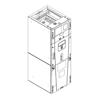
| Cabinet Construction | Galvanized Steel |
| Insulation | Foil Faced |
| Refrigerant | R-410A |
| Cooling Capacity | 48000 BTU |
| Voltage | 208/230V |
| Coil Type | Copper with Aluminum Fins |
Safety warnings and cautions for hazardous voltage, grounding, live components, refrigerant, and sharp edges.
Table specifying vapor and liquid line connection sizes for different models.
Instructions for preparing and brazing refrigerant lines, including safety notes.
Guidelines for routing, sloping, and connecting condensate drain lines.
Information on maximum wire lengths and steps for low voltage wiring connections.
Details on control board installation and wiring for horizontal right configurations.
Instructions for setting refrigerant type and other configuration jumpers.
Guidelines for high voltage power connection and selecting conduit entry points.
Explanation of how the system operates in various modes like cooling, heating, and defrost.
A comprehensive checklist to ensure all installation steps are completed correctly.