Do you have a question about the Ingersoll-Rand Variable Speed Voyager TZC036E3 and is the answer not in the manual?
Details the importance of safety advisories and defines the types of warnings used in the manual.
Discusses scientific research on man-made chemicals affecting the ozone layer.
Emphasizes responsible refrigerant handling, technician certification, and compliance with laws.
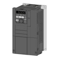
Describes the electric drive system primarily for controlling variable speed compressors.
Details the core control circuitry, including the interface module and signals.
Explains the interface module PCB, its function, LED display, and dip switch settings.
Covers the high-voltage portion controlling current and voltage output to the compressor motor.
Explains the Power Factor Correction solution for improving power factor and reducing emissions.
Describes the unique EMI filter for AC line filtering and reducing emissions.
Details the rectifier section that converts AC power to DC power.
Explains the DC bus as the intermediary power stage with film capacitors.
Describes the inverter section's function in creating AC output for the compressor motor.
Shows diagrams illustrating drive mounting locations for different unit models.
Describes how the interface module LED displays the requested compressor frequency command.
Explains how the interface module LED displays error or protection codes during abnormal states.
Details error and protection codes, their criteria, troubleshooting, and reset criteria.
| Brand | Ingersoll-Rand |
|---|---|
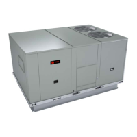
| Model | Variable Speed Voyager TZC036E3 |
| Category | Air Conditioner |
| Language | English |