Air2-BS200 | © 2020 Inim Electronics S.r.l.
9
4.1 Addressing of Air2-BS200
For secure deployment and operations of the wireless intrusion protection system Air2 it is necessary to refer
to the Installation and programming guide of the hardwired intrusion control panel in use.
1. Choose a suitable mounting placement.
2. Using a flat-bladed screwdriver in the enclosure screw location, push open the enclosure and sep-
arate the two parts.
3. Hold the base to the chosen mounting placement and mark the screw holes and tamper protection
position.
4. Pull the wires through the cable entry and wire up the transceiver.
5. Using the screws, secure the base and the tamper protection in position.
6. Enroll the device.
7. Re-attach the cover to the base and replace the enclosure screw.
"UUFOUJPO
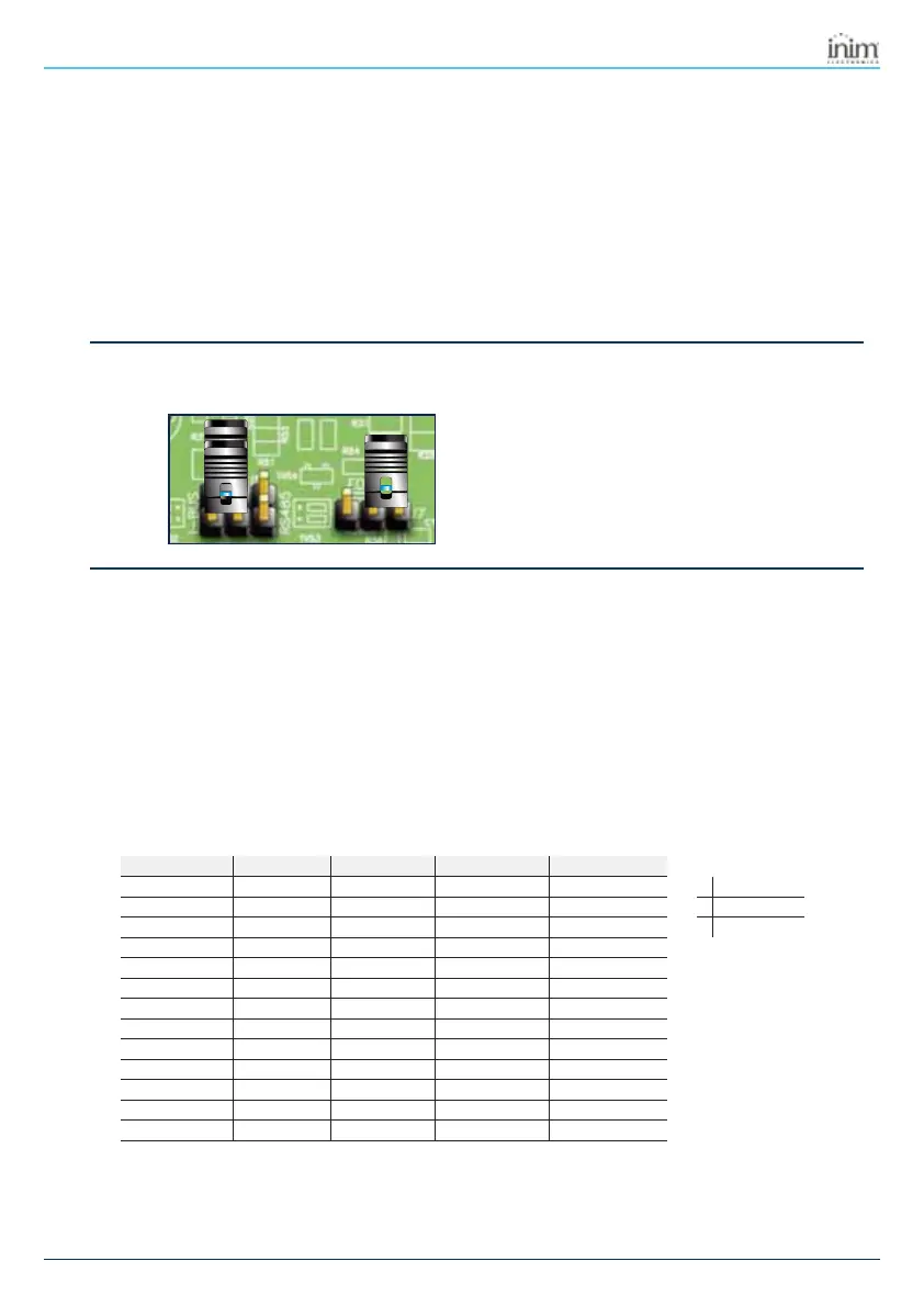
Do not change the setting of the jumpers on the connectors.
4.1 Addressing of Air2-BS200
During the enrolling phase the wireless transceiver Air2-BS200 is integrated into the intrusion control panel
INIM by simulating:
a reader, with the address programmed via the module itself (ADD), by means of buttons P1 and P2
on the PCB;
up to 10 expansion boards, at addresses ADD, ADD+1, ... ADD+9, to manage the terminals and to
be configured via the software project template
The address must be set during the programming phase of the reader. During this phase the address is indic-
ated by LEDs DL 1-4 in accordance with the following:
Reader address LED DL1 - red LED DL2 - blue LED DL3 - green LED DL4 - yellow
1 00 0 1
0 LED Off
2 00 1 0
1 LED On
3 00 1 1
L Flashing LED
4 01 0 0
5 01 0 1
6 01 1 0
7 01 1 1
8 10 0 0
9 10 0 1
10 10 1 0
11 10 1 1
12 11 0 0
13 11 0 1



 To Next Page