“OR”; the detector signals alarm status when smoke in the protected environment exceeds the pro-
grammed threshold (programmed as described for the ID100 model) or when the temperature within
the protected environment exceeds the programmed threshold (programmed as described for the
ID200 model). This operating mode, characterized by medium-high sensitivity, allows detection of
fires which generate a substantial amount of smoke but low heat emission (slow burning fires) as
well as fir es which generate high temperatures and low sm oke emission (chemical pr oducts).
“AND”; the detector signals alarm status when the smoke and temperature in the protected envi-
ronment exceed the programmed thresholds simultaneously (programmed as described for theID100
model and ID200 model respectively). This operating mode, characterized by a low sensitivity,
lowers the false alar m rate and is useful in applications where either the smoke or heat values in the
protected environment may increase without the risk of fire.
Note
Given the limited response, consider the conditions in the protected environment carefully
before selecting this operating mode.
“SMOKE”; the detector assumes the characteristics of the ID100 model
“HEAT”; the detector assumes the characteristics of the ID200 model
LED
The bicolour LED (360° viewing) indicates the detector status.
Green blinking at 30-second intervals: detector in standby status (i.e. operating properly).
Green blinking at 5-second intervals: detector in fault status. Further details regarding the cause of the
fault (high contamination level in the smoke chamber, detector component fault, etc.) can be obtained
through the EDRV2000 driver.
Red LED Onsolid: detector in alarm status.
“R” terminal
The detectors have an output (terminal “R”), for the connection of an alarm repeater LED. This LED will
activate when the detector it refers to triggers an alarm.
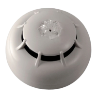
Description of the parts
A Detector
B Detector notch
C Thermal probe
D Red/green LED
E Optical chambe r
F Technical specifications/serial-number sticker
G Removable serial-number stickers
H Cover removing hooks
I Optical chambre removing hooks
J Base
K Base notch 1
L Base notch 2
M “+” terminal
N “-” terminal
O “R” terminal
P Short-circuit reed
Q Screw locations
Installation
Note
For information regarding device placement, coverage and method of installation, refer to the
established standard regulations and codes relating to Automatic fire-detection systems.
Iris series detectors are compliant with EN54-7: Smoke detectors – Point detectors using the
scattered light principle, light transmission or ionization (ID100 and ID300 models only) and
EN54-5: Heat detectors – point detectors (forID200 and ID300 models only),.
The detectors are supplied with protective covers which help to protect them against minor damage and
dust contamination which may occur dur ing the installation phase. The covers should not be removed
until the system is ready to start up.
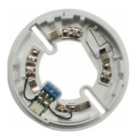
The detectors can be used with one of the following compatible mounting bases:
EB0010; standard base
An example of installation using standard bases is shown opposite.
EB0020; relay base
Appropriate when the detector is to be connected to an intrusion control panel or to a control panel
using 4 wir es.
Note
The two removable serial-number stickers should be taken off and one should be attached to
the mounting ba se and the oth e r to th e installation layou t.
Once the base is located properly in its placement, place the detector unit onto the base and, with mini-
mum force, turn it clockwise until the detector notch [B] aligns with the base notch [K] (in order to atta ch
the detector to the base); turn it still further until notch [B] aligns with the second base notch [L] (inorder
to allow the base to engage with the detector contacts).
Usingthe EDRV2000 driver
The EDRV2000 driver allows you to change the operating parameter s of the detectors, check the con-
tamination level of the smoke chambers and also obtain accurate diagnostic data. It can operate through
the USB port of a computer furnished with the relative software programme, or can function auto-
nomously by way of the battery housed inside.
Each detector is capable of retaining memory (smoke and/or temperature depending on the model) of
the 5 m inutes prior to an alarm. Therefore, if an alarm occurs, it will be possible toobtain information
regarding the onset of the fire by simply connecting the EDRV2000 driver to the detection line.
For further information and details regarding use of the EDRV2000 driver, refer to the respective hand-
book.
Testing and maintenance
After installation and during periodic maintenance inspections, you must carry out the following ope-
rations on each detector:
Check the LED; if the LED blinks at 5 second intervals, the detector is in fault status. This may be due
to dust contamination. If after cleaning, this condition persists, remove the faulty detector and replace it
with a new one. The EDRV2000 driver will assist you in finding the cause of faults.
Opticalsmokedetectortest; smoke detectors should be tested immediately after installation and perio-
dically during maintenance inspections in accordance with the established standard regulations and
codes in force. To test smoke detectors, use an approved test aerosol strictly in accordance with the
accompanying instructions.
Ensure that the smoke inlet ports to the smoke detection chamber are not blocked. Check the con-
tamination level of the smoke detection chamber via the EDRV2000. If the contamination level is high,
detach the detector from its mounting base and open the chamber then, using a small, soft-bristle brush
or hand-held vacuum cleaner r em ove all dust particles from inside and around the sm oke detection
chamber.
Free the protection mesh from all contaminants.
Heat detector test; using a suitable device (e.g. hairdryer), create heat in the vicinity of the detector,
then work through the steps described in the device instruction sheet. During each periodic m aintenance
inspection, ensure that the heat element is intact and that is not obstructed by dust or paint. If it is, using a
small, soft-bristle brush or hand-held vacuum cleaner remove all contaminants.
Technicalspecifications
Model ID10 0 ID200 ID30 0
Power supply from 10 to 30 V
Current draw in standby 90µA 70µA 90µA
Current draw in alarm Max 40mA
Current draw byt he “R” output
(internally limited)
Max 14mA
Dimensions (DxH, standard base
included)
110 x 46 mm 110 x 54 mm
W eight
160g, standard base included
91g, without base
Environmentalconditions
Temperat ure from -5 to +40 °C
Rela tive humidity ≤ 95 % without condensation
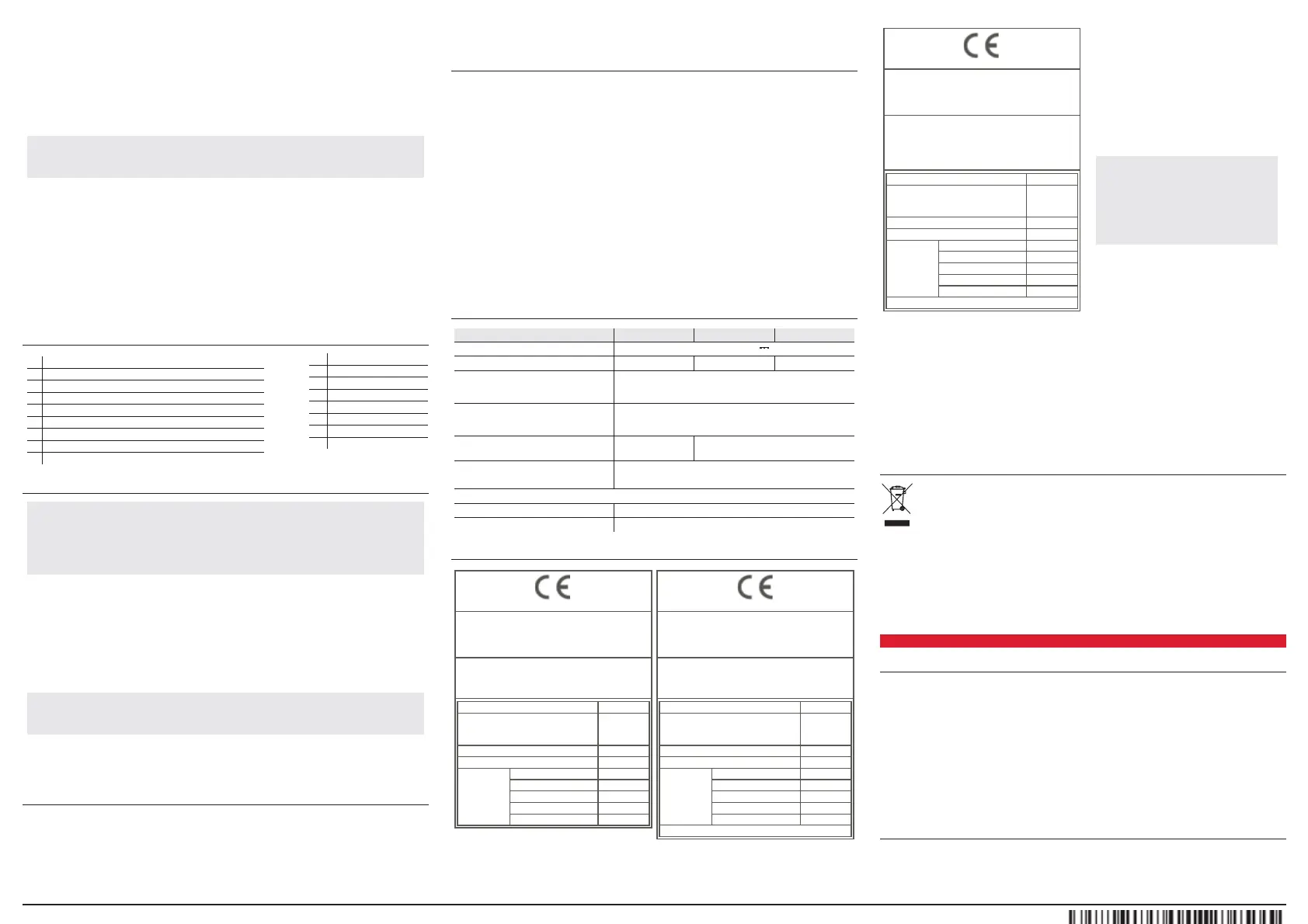
CE mark
0051
IN IM Electronicss.r.l.
Via Dei Lavoratori 10 -Fraz.Centobuchi
63076 Monteprandone (AP)- Italy
10
0051-CPR-187
5
EN 54-7:2000 + A1:2002 + A2:2006
ID100
Conventional optical smoke dete ctorforfire det ection
and fire alarm systems installed in buildings
Essential chara
cteristics Performance
Nominal activation con-
dition/ sensitivity, response delay
(re sponse time) and performanc
e
under fire conditions
PASS
Operation al reliability PASS
Tolerance to supplyvoltage PASS
Durabilityof
operational
reliability:
Temperature resistance PASS
Vibration resistance PASS
Humidityresi stance PASS
Corrosion resistance
PASS
Electrical stability PASS
0051
IN IM Electronicss.r.l.
Via Dei Lavoratori 10 -Fraz.Centobuchi
63076 Monteprandone (AP)- Italy
10
0051-CPR-187
4
EN 54-5:2000 + A1:2002
ID200
Conventional classP heat detectorforfire detection
and fire alarm systems installed in buildings
Essential charact
eristics Performance
Nominal activation con-
dition/ sensitivity, response delay
(re sponse time) and performance
u
nderfire conditions
PASS
Operation al reliability PASS
Tolerance to supplyvoltage PASS
Durabilityof
operational
re
liability:
Temperature resistance PASS
Vibration resistance PASS
Humidityresi stance PASS
Corrosion resistance PA
SS
Electrical stability PASS
Detectorclass(EN54-5): A1R orB
0051
INIM Electronicss.r.l.
Via Dei Lavoratori 10 -Fraz.Centobuchi
63076 Monteprandone (AP)- Italy
10
0051-CPR-187
3
EN 54-5:2000 + A1:2002
EN 54-7:2000 +A1:2002 + A 2:2006
ID300
Conventional multicriteria optical smoke and classP
heat detector forfire detection and fire alarm systems
installe
d in buildings
Essential characteristics Performance
Nominal activation con-
dition/ sensitivity, response delay
(
response time)and performance
under fire conditions
PASS
Operational reliability PASS
Tolerance to supplyvoltage P
ASS
Durabilityof
operational
reliability:
Temperature resistance PASS
Vibration resistance PASS
Humidityresi sta
nce PASS
Corrosion resistance PASS
Electrical stability PASS
Detectorclass(EN54-5): A1R orB
Documents forthe users
Declarationsof Perform ance,Declarationsof Conformity
and Certificatesconcerning to Inim Electronics S.r.l.pro-
ducts m ay be downloaded free of chargefrom the web
address www.inim.biz, g etting accessto Extended
Access and then selecting "Certifications" or requ ested to
thee-mail address info@inim .biz orrequestedby ordi-
nary mailto the address shownin this manual.
Manualsm ay be downloaded free of chargefrom the
web add resswww.inim .biz, ge tting accessto Extended
Access and th en selecting "M an uals".
Warnings and limitations
Irisseries detectors must be used e xclusivelywith
fullycompliant, compatible controlpanels. Detectors
may notprovide timely warning of fire if coverage is
limite d by la rg e ob stru ctio n s (p illa rs, la rge ma chin e ry,
etc.). Wh e n in st a llin g or wo rkin g on a fire d e te ctio n
system, always referto and complywith the esta-
blished standard regulationsand codes. Appro-
priate fire-risk assessmentshould be undertaken to
determine the type ofdetectors required and their
placements.
Manufacturer's details
Manufacturer:In im ElectronicsS.r.l.
P roduction plant:Centobuchi, viaDeiLavoratori 10
63076 M onteprandone (AP),Italy
Tel:+39 0735 705007
Fax:+390735 734912
e-mail: info @ in im .b iz
Web:www.inim.biz
The persons authorized by the manufacturer to repair
or replace th e parts of this system, hold authorization to
workon Inim Electronics branddevices only.
About this manual
Manual code:D CMIIN1PID
Revision:250
Copyright:the inform ation contained in this document
isthe sole propertyof Inim ElectronicsS.r.l . No part may
be copied withoutwrittenauthorization fromInim Elec-
tronicsS.r.l.. Al lrightsreserved.
WEEE
lnformative notice r egarding the disposal of electrical and electronic equipment (applicable in
countries with differentiated waste collection systems)
The crossed-out bin symbolon the equipment oron its packaging indicatesthattheproductm ustbe disposed
ofcorrectly at the end of itsworking life and should never be disposed of together with generalhousehold
waste.Theuser, therefore, m usttake the equipmentthathas reached the end of its working life to the appro-
priate civic am enities sitedesignated to thedifferentiatedcollection of electricaland electronic waste. As an alternative to
theautonomous-m anagement ofelectricaland electronic waste, you can hand over the equipment you wishto dispose
oftoa dealerwhen purchasing new equipm entof the same type. You arealso entitled toconveyfor disposalsmallelec-
tronic-wasteproducts with dimensions of lessthan 25cmtothe premisesof electronic retail outlets with sales areasof at
least400m2, free of charge and withoutany obligation to buy.Appropriatedifferentiated wastecollection for the sub-
sequent recycling of the discarded equipment,its treatmentand itsenvironmentally compatible disposalhelpsto avoid
possible negative effects on theenvironment and on health and favoursthe re-use and/or recycl ing of the mate rials it is
made of.
ES
Descripcióngeneral
Los detectores de la serie Iris son capaces de detectar la presencia de algunos productos de combustión
y por lo tanto la generación de puntos de incendio.
Los parámetros de funcionamiento de los detectores pueden ser modificados y adecuados a las con-
diciones ambientales a través del dispositivo EDRV2000 entregado por Inim Electronics. A través de
este dispositivo es posible programar los detectores así como valorar la contaminación y el fun-
cionamiento. Para mayores detalles ver el apartado “Uso del driver EDRV2000”.
El detector, que en condiciones de stand-by posee una baja absorción, 80µ A, en caso de alarma
aumenta la corriente absorbida hasta un máximo de 40mA, indicando de este modo el peligro a la cen-
tral de control.
Inim Electronics pone a disposición tres modelos de detectores convencionales de la serie Iris que pue-
den reconocerse a través de la etiqueta de datos de la matrícula que se encuentra situada sobr e la parte
trasera. Esta etiqueta lleva un número de serie unívoco que identifica al dispositivo.
Modelos
ID100
Detector óptico dotado de una cámara de prueba basada en el efecto de la difusión de la luz (efecto Tyn-
dall). Para garantizar la eficacia no deben existir obstáculos en la entrada de aire en el interior de la
cámara de prueba y el detector no debe ser expuesto directamente a cor r ientes de aire.
Manuale d'istruzioni/ Instruction m anual/ Manual de instrucciones /Notice d’instructions Inim Electronics S.r.l. © 2020 DCMIIN1PID-250-20200618
 Loading...