M O D E V A R e f e r e n c e M a n u a l P a g e 14 o f 16
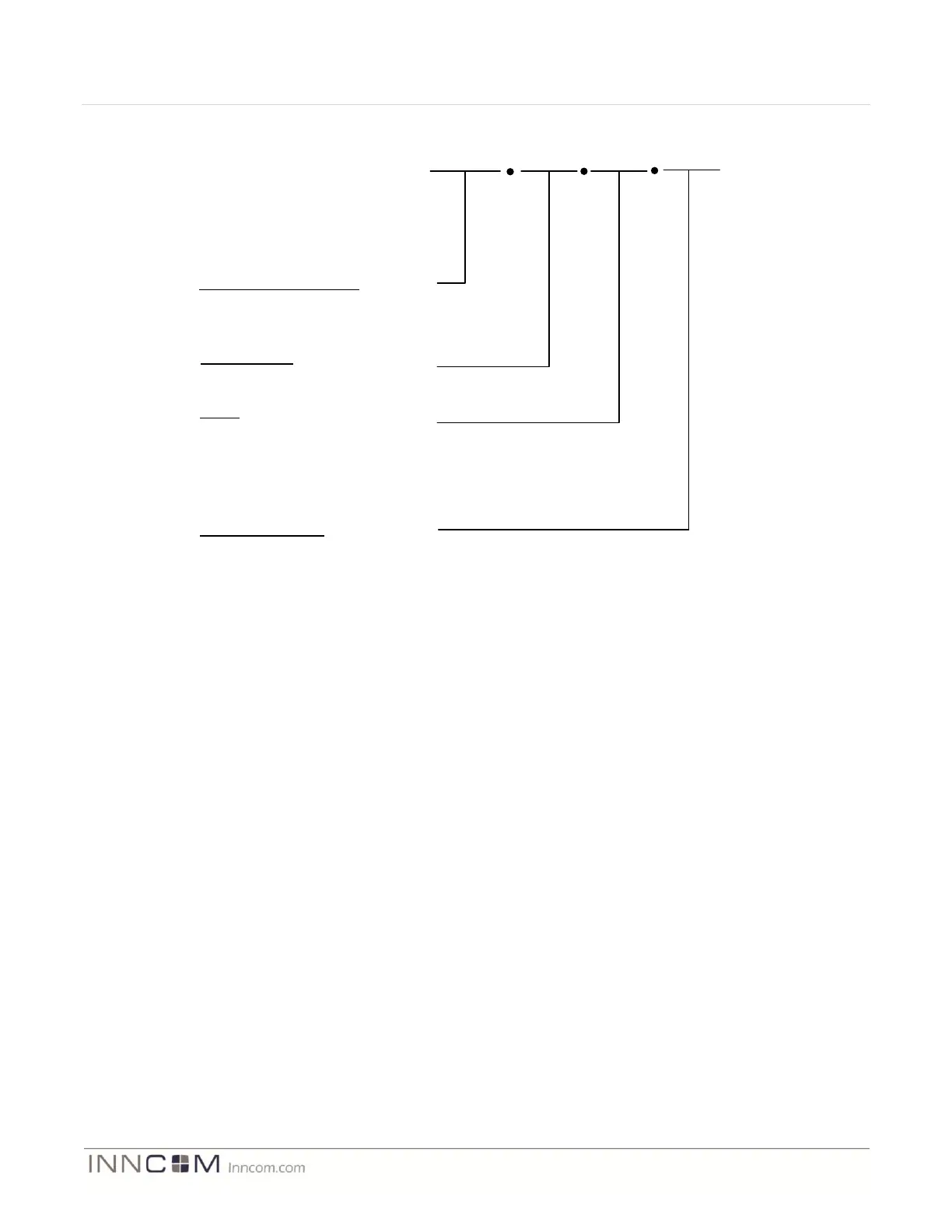
03-7060
Assembly Part Number
03-7060 – Single Gang Assembly
03-7061 – Double Gang Assembly
03-7062 – Triple Gang Assembly
GHS1
Switch Model
Defined by project
R0
Frame Plate Color
WH = White
BK = Black
AL = Almond
XX = Custom Pantone Color
Radio
R0 = No Radio
R1 = Layer-1 Radio (02-9994.L1)
R2 = Layer-2 Radio (02-9894.L2- Not available)
R3 = Reserved for future application
R4 = Reserved for future application
R5= Reserved for future application
WH
Figure 9 User Interface Assembly Ordering Part Number
Examples:
03-7060.GHS1.R1.WH = MODEVA user interface assembly switch #1 designed for the Grand Hyatt New York
project that includes the CC2430 based radio circuit and a white framing plate. “GHS1” further defines the
attributes of the Touch User interface PCB model (ex. GS-765.XXX) in the following:
Number of capacitive touch keys or sliders
Locations of capacitive touch keys
Number of indicator LEDs
LED locations
LED colors
This information is found in the 03-7060.GHS1 Hardware Guide. Note that when a double and triple gang
assembly is designed (03-7062.xxx.xx.xx) it becomes more critical to refer to the hardware guide that defines the
touch user interface attributes for the left gang, center gang, and right gang. Again note that in a double and triple
gang assembly two and three touch user interface PCBA’s are required, but always only one logic board PCBA is
required.
03-7061.GHS2.R0.WH = A double gangMODEVA assembly configured for the Grand Hyatt Switch position #2
that does not include the CC2430 radio circuit, uses a white framing plate, and uses a GS-765.STD in the left
position, and a GS-765.NL01 in the right position. (See GS-765.STD and GS-765.NL01 hardware guide for specific
details of the touch user interface).