47
48
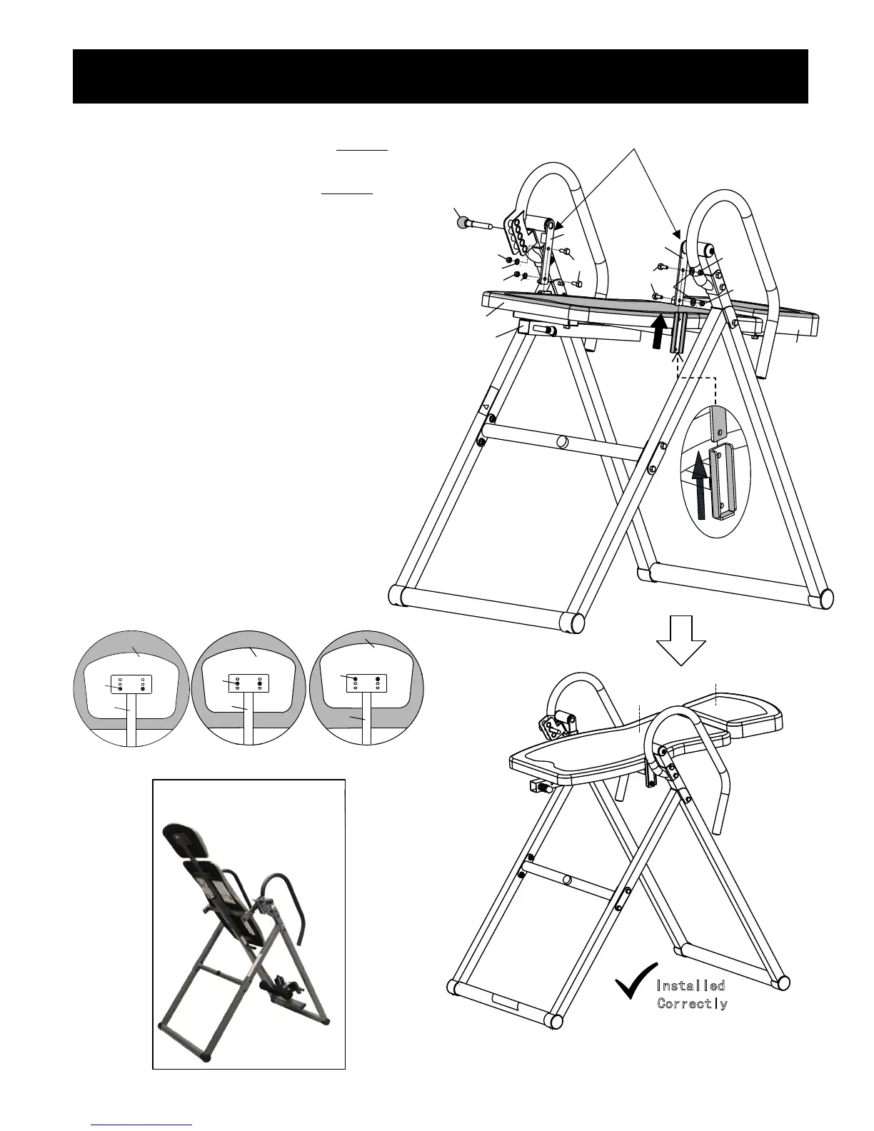
Attach the completed Backrest Assembly
(2&47&48) to the Connecting Brackets
(11R&11L) using 4 Bolts (29), 4 Flat
Washers (19) and 4 Lock Nuts (21).
Screw the Angle Selector Pin (14) into
the Incline Position 15 hole and tighten.
Before Installation, Please NOTE:
Connecting Brackets (11R&11L) MUST
be pointing downward and the
completed Backrest Assembly MUST
be attached from below and up into the
connecting brackets or the table will
not invert properly.
Step 3 – Backrest Assembly to Base Frame
8
TIGHTEN ALL NUTS, BOLTS, AND
SCREWS AT THIS TIME
Connecting Brackets Must Point Downward
When Attaching Backrest Pad Assembly
Headrest Pad Adjustment: To adjust
the Headrest Pad (48), unscrew Bolts
(40) and Washers (57) and remove it
from the Backrest Support Tube (2).
Move the Headrest Pad (48) to the
position desired on the Backrest Support
Tube (2) and screw Bolts (40) and
Washers (57) to secure the Headrest
Pad (48) into place.
Installed Incorrectly
X
Installed Incorrectly
X
48
40
2
48
40
2
Front
Rear
47
48
Installed
Correctly
48
40
2
Fr ont
Rear
X
 Loading...