AMTEK Version 7.4 2019-01 Page 23 ©Inomatic 2017-2019
Switch off the power first before you change any jumpers!
Wait a while for the capacitors to discharge! High voltage!
If the LED bars do not light up completely on one or both sides, then:
It is necessary to adjust the matching of the antenna loops. The AMPRO 700V7.5
processor board is designed to be used for all AMTEK systems. Since every
AMTEK system shows slightly different antenna characteristics, the board allows
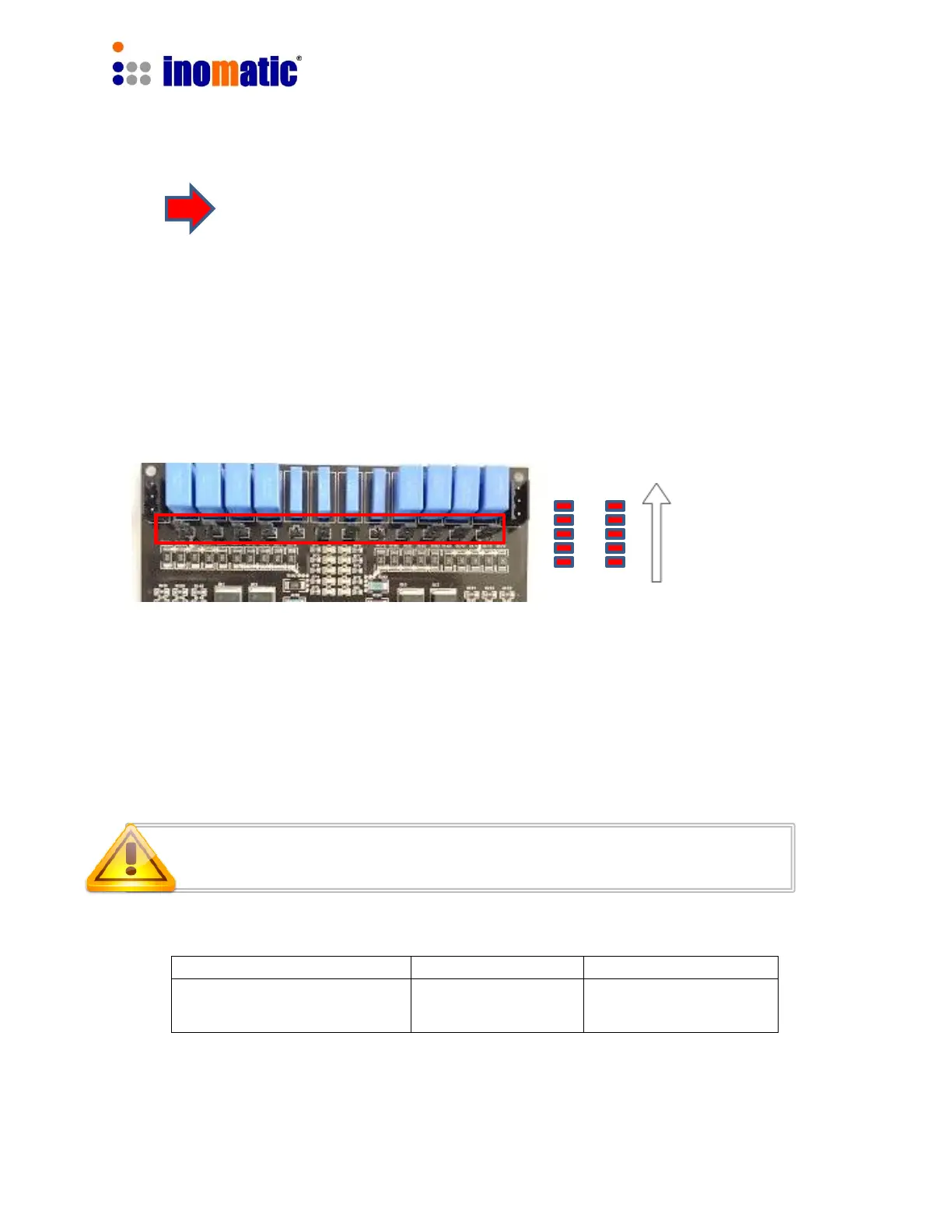
the selection of different capacitors for each antenna loop by inserting the
respective jumpers. The matching capacitors are located at the upper part of the
board.
The matching Level is shown by the LED bars TX1 and TX2:
If the antenna is mismatched, not all of the 5 LEDs of LED bars TX1 and TX2 will light up.
In that case, the TX resonance of the upper and lower loop can be modified by
changing the matching capacitance through the 6 jumpers in the relevant matching
circuits (refer to default setting below).
Matching of the upper loop
Matching of the lower loop
Increasing
quality of
matching
 Loading...