AMTEK Version 7.4 2019-01 Page 30 ©Inomatic 2017-2019
One “Master” can drive several “Slaves”. In order to proper
terminate the Master/Slave Sync bus-cable, the Jumper
J17 or 18 has to be inserted at the beginning of the sync
bus-cable (usually Master antenna) and the end of the bus-
cable (last Slave board).
To set to Master mode (the default mode), put the jumper
J15 in position 2 and 3. For the antenna to operate in Slave
mode put the jumper in position 1 and 2.
Please do not turn on the power before the configuration is ready. First switch on
the power supply for the “Slave” antenna and then the power supply to the
“Master” antenna.
When using hardware synchronization, you must set the synchron value to 0 for
all “Slave Processor” boards by means of the infoNet software (see
infoNetManual). Shifting the Synchron value for the master Processor will
automatically shift the Synchron value of all connected slave antennas.
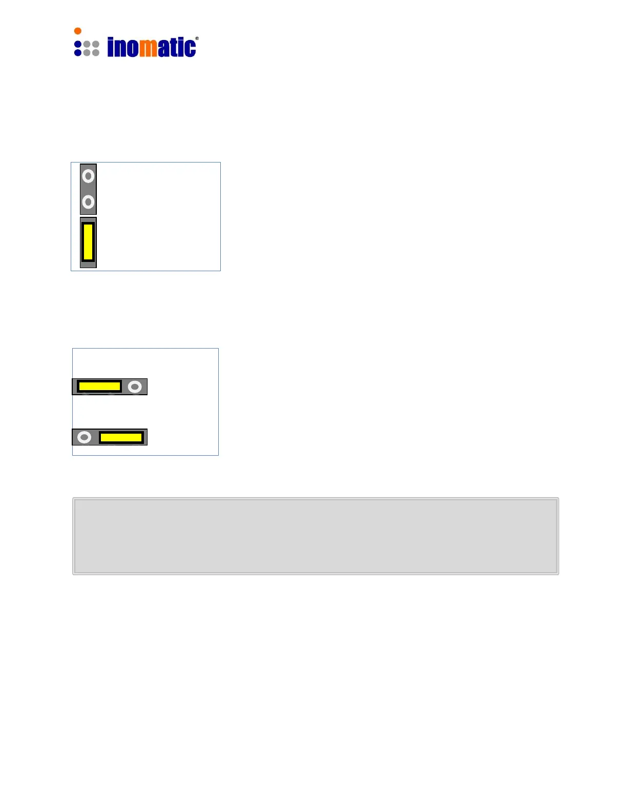
J17 & 18
Sync Bus Termination
All other slaves
Both end of the
sync cable (bus)
 Loading...