AMTEK Version 7.4 2019-01 Page 8 ©Inomatic 2017-2019
Table 2.2 Processor board's relevant components for connection and tuning
LED bar for upper TX loop
LED bar for lower TX loop
Real Time Clock battery 3V
Flashing Normal Operation
Indicator for Master/Slave
Jumpers 14 (Download Firmware)
The firmware of the AM Processor
board V7.4 can be updated via the
infoNet V5 software.
For more details see Software Manual
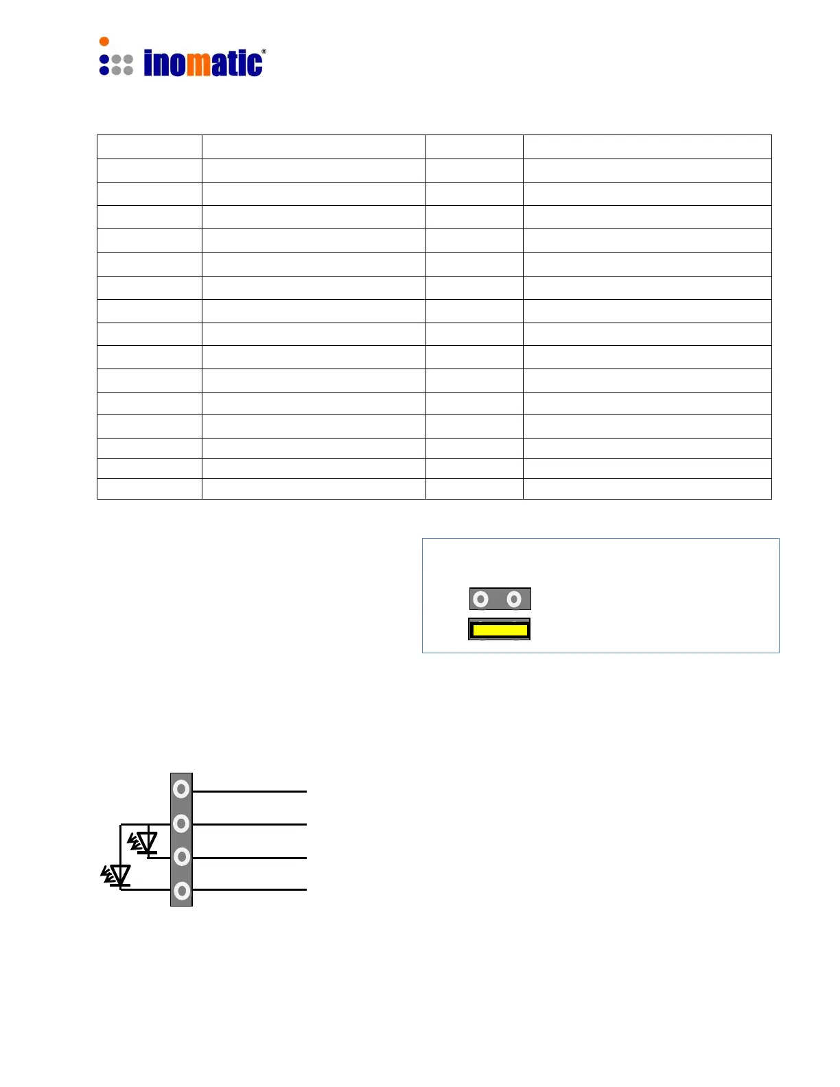
LED Light connector X5
The AM Pro-line V7.4 board allows the connection of a two color LED top-light.
GND
12V
LED1 (ON LED, active low)
LED 2 (Alarm LED, active low)
Maximum current for LED1 and LED 2 is 200mA
Normal Operation
Download Firmware
 Loading...