CLS FUSION Montage- und Betriebsanleitung
CLS FUSION Mounting and Operating Instructions
43
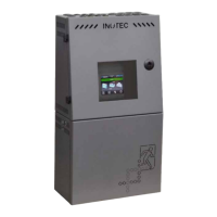
8.4.1. Informationsbereich
Hier ist der Gerätetyp „CLS FUSION“ zu erkennen. In der
Mitte bendet sich das Tagesdatum mit aktueller Uhrzeit.
Wird ein USB Stick von der Anlage erkannt, wird er rechts
neben der aktuellen Uhrzeit im Informationsbereich
symbolisiert. Laden oder speichern sie Daten vom USB
Stick, so fängt dieser an zu blinken.
8.4.2. Statusanzeige
Die Statusanzeige zeigt den jeweiligen Status der Anlage
an. Dieser kann zum Beispiel zwischen Betrieb (Grün),
einem Ausfall Haupt- oder Unterverteiler (Gelb) oder
einer Störung (Rot) je nach Zustand wechseln.
Beispiele:
Betrieb (Grün)
Betrieb
Ausfall Haupt.- oder Unterverteiler (Gelb)
Netzausfall Hauptverteiler
Störung (Rot)
Störung
Platz
8.4.3. Funktionsschaltächen
Die „Funktionsschaltächen“ sind in drei Bereiche
(Leuchten, Batterie und Komponenten) unterteilt.
Durch Betätigen der jeweiligen Schaltäche gelangt
der Anwender in entsprechende Untermenüs. Hier sind
detaillierte Kongurationen jeweiliger Bereiche einzuse-
hen beziehungsweise vorzunehmen.
8.4.1. Information display
The device type “CLS FUSION” is shown here. Current
date and time are displayed in the middle. If a USB stick
is detected by the system, this is indicated on the right
beside the current time. If you load or save data from the
USB stick, it begins to ash.
8.4.2. Status display
The status display shows the current status of the sys-
tem. It can change between operation (green), mains or
sub-DB failure (yellow) or a failure (red), depending on
the current status.
Examples:
Operation (Green)
Operation
Mains or sub-DB failure (Yellow)
Mains failure
Failure (Red)
Failure
Slot
8.4.3. Function buttons
The function buttons are divided into three areas: lumi-
naires, battery and components. Activating the appro-
priate button takes the user to the corresponding sub-
menu. Detailed congurations of the respective areas
can be checked and/or set up here.
 Loading...