6
ELS/SV Montage- und Betriebsanleitung
ELS/SV Mounting- and Operating Instructions
Tests können jederzeit manuell ausgelöst werden und
sind zudem, was Zeitpunkt und Wiederholzyklus betrifft,
frei programmierbar.
Drei potentialfreie Kontakte (3x Schließer) zur externen
Fehlermeldung/Statusanzeige sind vorhanden.
Jede ELS/SV kann zudem serienmäßig über eine Bus-
Leitung mit anderen Geräten (Modem, PC...) zur Anzeige
und Speicherung der Gerätekonfiguration und aller Mel-
dungen verbunden werden.
4.1 Funktionsprinzip
Jedes ELS/SV Gerät bietet die Möglichkeit, bei Anschluss
von Leuchten mit INOTEC J-SV EVG oder J-SV Module
jede einzelne an das Gerät angeschlossene Leuchte auf
ihre Funktion zu überwachen. Dazu müssen die Leuchten
adressiert sein und am jeweiligen Stromkreis angemel-
det werden. 8. 4.3 Leuchten auf Wandler anmelden
– Seite 30
Unabhängig davon überwacht jede Anlage den Batte-
riekreis (Ladeteil, Batterie) selbsttätig und zeigt Fehler
automatisch an.
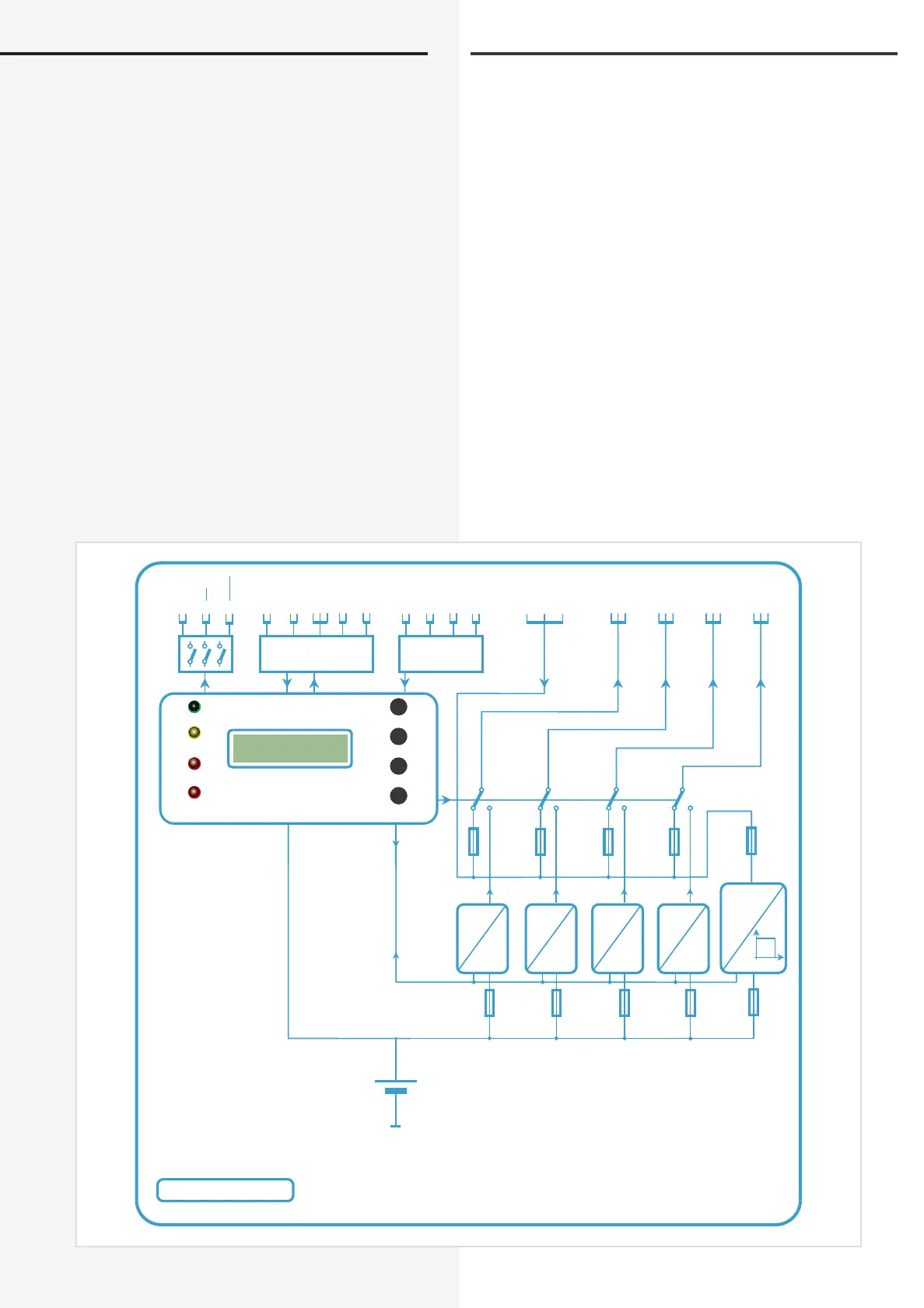
Prinzipschaltbild
Tests can be released manually at all times and are free
programmable regarding starting time and repeat cycle.
Three volt-free contacts (3 x no) for external status-/fail-
ure display are part of the ELS/SV system.
To link a system to other ELS/SV systems and/or other
components (Modem / PC) is an option automatically
catered for on the terminal strip of the ELS/SV. This allows
data storage and visualisation of all relevant information.
4.1 Functional principle
Each ELS/SV–system offers the possibility, if luminaires
with INOTEC J-SV EVG or J-SV modules are connected,
to monitor each and every individual lamp connected.
For this, the luminaires must be addressed and allocated
to the respective output. 8. 4.3 Allocate luminaire
addresses to output circuit – page 30
Apart from this every system monitors permanently the
internal battery circuit (charger, battery, connections)
and displays automatically every malfunction.
Block diagram
INOTEC ELS SV
AC
DC
DC
DC
DC
DC
DC
DC
DC
DC
5 AT10 AT10 AT10 AT10 AT
24V / Pb
Failure
Operation
Batt.-Operation
Remote Control
Light Switch
Indicator
output
Operation
Batt.-Operation
Failure
Charging failure
Menue
Enter
Change
Test
FS 24V RTG
B
SL
CH1 CH2 CH3 CH4
230V / AC
50 / 60 Hz
4
N L
PE
3
N L
PE
L N L NL NL N
3,15 AT
3,15 AT
3,15 AT3,15 AT
3,15 AT
1 65432
2
N L
PE
1
N L
PE
PE LN
 Loading...