www.inovelli.com/lzw31-sn/setup contact@inovelli.com page 4
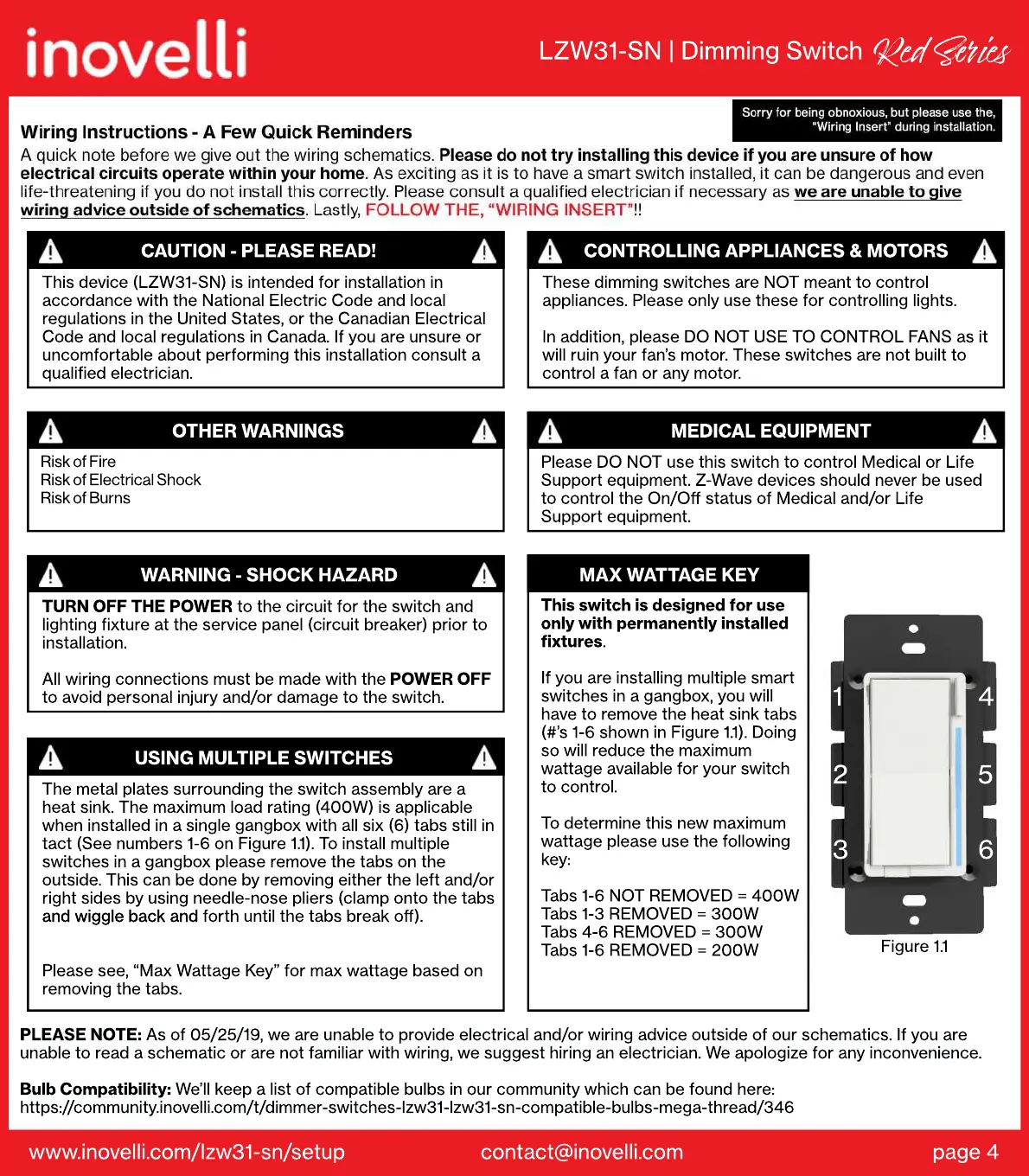
Figure 1.1
6
5
4
3
2
1
This switch is designed for use
only with permanently installed
fixtures.
If
If you are installing multiple smart
switches in a gangbox, you will
have to remove the heat sink tabs
(#’s 1-6 shown in Figure 1.1). Doing
so will reduce the maximum
wattage available for your switch
to control.
T
To determine this new maximum
wattage please use the following
key:
Tabs 1-6 NOT REMOVED = 400W
Tabs 1-3 REMOVED = 300W
Tabs 4-6 REMOVED = 300W
Tabs 1-6 REMOVED = 200W
MAX WATTAGE KEY
Please DO NOT use this switch to control Medical or Life
Support equipment. Z-Wave devices should never be used
to control the On/Off status of Medical and/or Life
Support equipment.
MEDICAL EQUIPMENT
CONTROLLING APPLIANCES & MOTORS
These dimming switches are NOT meant to control
appliances. Please only use these for controlling lights.
In addition, please DO NOT USE TO CONTROL FANS as it
will ruin your fan’s motor. These switches are not built to
control a fan or any motor.
USING MULTIPLE SWITCHES
The metal plates surrounding the switch assembly are a
heat sink. The maximum load rating (400W) is applicable
when installed in a single gangbox with all six (6) tabs still in
tact (See numbers 1-6 on Figure 1.1). To install multiple
switches in a gangbox please remove the tabs on the
outside. This can be done by removing either the left and/or
right sides by using needle-nose pliers (clamp onto the tabs
and wiggle back and
and wiggle back and forth until the tabs break off).
Please see, “Max Wattage Key” for max wattage based on
removing the tabs.
WARNING - SHOCK HAZARD
TURN OFF THE POWER to the circuit for the switch and
lighting fixture at the service panel (circuit breaker) prior to
installation.
All wiring connections must be made with the POWER OFF
to avoid personal injury and/or damage to the switch.
Risk of Fire
Risk of Electrical Shock
Risk of Burns
OTHER WARNINGS
CAUTION - PLEASE READ!
This device (LZW31-SN) is intended for installation in
accordance with the National Electric Code and local
regulations in the United States, or the Canadian Electrical
Code and local regulations in Canada. If you are unsure or
uncomfortable about performing this installation consult a
qualified electrician.
PLEASE NOTE: As of 05/25/19, we are unable to provide electrical and/or wiring advice outside of our schematics. If you are
unable to read a schematic or are not familiar with wiring, we suggest hiring an electrician. We apologize for any inconvenience.
Bulb Compatibility: We’ll keep a list of compatible bulbs in our community which can be found here:
https://community.inovelli.com/t/dimmer-switches-lzw31-lzw31-sn-compatible-bulbs-mega-thread/346
LZW31-SN | Dimming Switch
Red Si
 Loading...