www.inovelli.com/lzw31-sn/setup contact@inovelli.com page 7
* Please make sure your HUB
supports these features. See
website for more details.
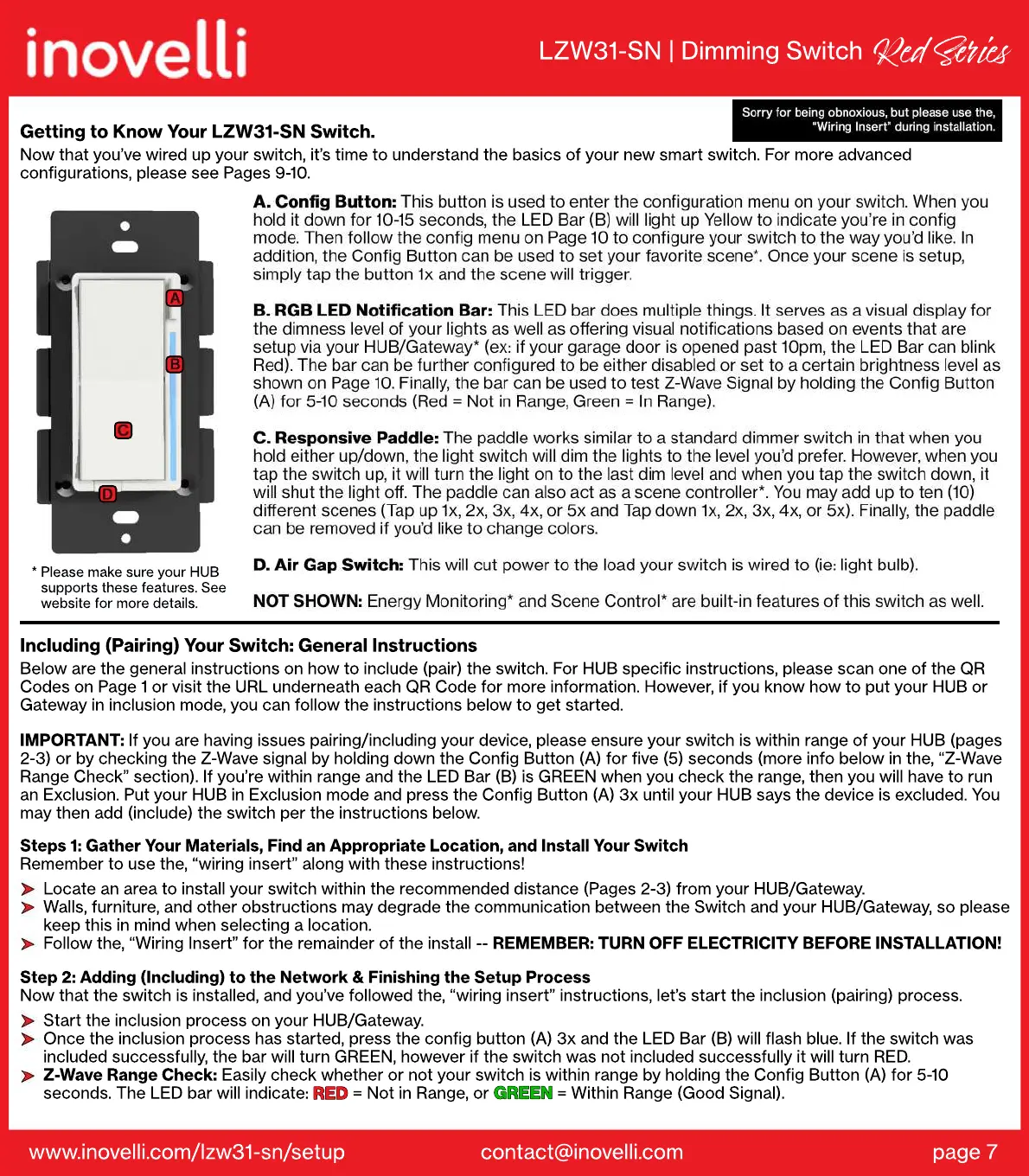
Getting to Know Your LZW31-SN Switch.
Now that you’ve wired up your switch, it’s time to understand the basics of your new smart switch. For more advanced
configurations, please see Pages 9-10.
LZW31-SN | Dimming Switch
Red Si
Start the inclusion process on your HUB/Gateway.
Once the inclusion process has started, press the config button (A) 3x and the LED Bar (B) will flash blue. If the switch was
included successfully, the bar will turn GREEN, however if the switch was not included successfully it will turn RED.
Z-Wave Range Check: Easily check whether or not your switch is within range by holding the Config Button (A) for 5-10
seconds. The LED bar will indicate: RED = Not in Range, or GREEN = Within Range (Good Signal).
GREEN
RED
Step 2: Adding (Including) to the Network & Finishing the Setup Process
Now that the switch is installed, and you’ve followed the, “wiring insert” instructions, let’s start the inclusion (pairing) process.
Locate an area to install your switch within the recommended distance (Pages 2-3) from your HUB/Gateway.
Walls, furniture, and other obstructions may degrade the communication between the Switch and your HUB/Gateway, so please
keep this in mind when selecting a location.
Follow the, “Wiring Insert” for the remainder of the install -- REMEMBER: TURN OFF ELECTRICITY BEFORE INSTALLATION!
Steps 1: Gather Your Materials, Find an Appropriate Location, and Install Your Switch
Remember to use the, “wiring insert” along with these instructions!
IMPORTANT: If you are having issues pairing/including your device, please ensure your switch is within range of your HUB (pages
2-3) or by checking the Z-Wave signal by holding down the Config Button (A) for five (5) seconds (more info below in the, “Z-Wave
Range Check” section). If you’re within range and the LED Bar (B) is GREEN when you check the range, then you will have to run
an Exclusion. Put your HUB in Exclusion mode and press the Config Button (A) 3x until your HUB says the device is excluded. You
may then add (include) the switch per the instructions below.
Including (Pairing) Your Switch: General Instructions
Below are the general instructions on how to include (pair) the switch. For HUB specific instructions, please scan one of the QR
Codes on Page 1 or visit the URL underneath each QR Code for more information. However, if you know how to put your HUB or
Gateway in inclusion mode, you can follow the instructions below to get started.
 Loading...