7/25/19 357-05177-01 Rev A © Inovonics, 2019 - www.inovonics.com
EN1210 Family Single Input Universal
Installation Instructions
1 Overview
The Inovonics EN1210 single input universal is designed for use
with almost any standard contact or sensor. Continuous check-
ins ensure reliability.
The single input universal is available in North America, Australia
and New Zealand; the radio frequency band has been
configured for the appropriate geographic area at the factory.
The single input universal is available in the following
configurations:
Note: For UL 2560 installations, refer to the EN6080 Area
Control Gateway Installation Instructions.
1.1 Maximum Number of Repeaters for a UL
2560 Installation
To achieve the 99.99% alarm message reliability required for UL
2560 compliance, system installations must operate within the
following limits for end device and repeater counts.
1.2 Inovonics Contact Information
If you have any problems with this procedure, contact Inovonics
Wireless technical services:
• E-mail: support@inovonics.com.
• Phone: (800) 782-2709.
1.3 Single Input Universal Internal Components
Figure 1 Single input universal components
1.4 What’s In The Carton
• Three wall mount screws.
• Three wall mount anchors.
• Two selection jumpers.
• One 3.0V lithium battery.
2 Installation and Startup
2.1 Installation Notes
• These products are designed to be installed and maintained
by professional security technicians.
• Products are intended for indoor use.
• Manually test all products weekly.
2.2 Install the Battery
1. Pry the top lip of the mounting bracket up, and lift the bracket
off of the transmitter.
2. Use your thumb to depress the housing release tab on the
bottom of the transmitter; separate the housing.
3. Install the new battery.
4. Press the reset button to initialize the transmitter.
2.3 Select Input Type
The N/O-N/C selection pins allow the choice of a normally open
or normally closed state for the contact circuit wired to the input
terminal. The transmitter is shipped set for normally closed, with
no selection jumper on the N/O - N/C selection pins. If you will be
using the product in a normally closed state, skip to section 2.4,
“Register the Transmitter”; if you will be using the product in a
normally open state, you will need to configure the transmitter:
1. Place a selection jumper on the N/O- N/C selection pins to
select normally open.
2. Press the reset button to complete configuration.
2.4 Register the Transmitter
Transmitters must be registered with the system in order to be
monitored and supervised. EN1210 transmitters send a check-in
message every three minutes; EN1210-60 transmitters send a
check-in message every 60 minutes; EN1210-240 transmitters
send a check-in message every 240 minutes. Each transmitter
has a unique factory-programmed identification number. Refer to
the receiver installation instructions for details on registering a
transmitter.
Note: For UL 2560 installations, transmitters must have a
minimum check-in time of 60 minutes.
1. When prompted by the receiver to reset transmitter, press
the reset button.
2. Replace the cover.
3. Test the transmitter by activating each of the conditions and
ensuring an appropriate response.
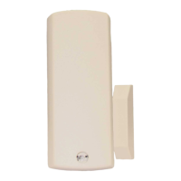
2.5 Mount the Transmitter
1. Mount the bracket on the wall with the screws provided.
Figure 2 Mount the bracket
2. Clip the transmitter onto the bracket. Hook the bottom catch
first, then press the top into place.
Part # Check-In
EN1210 3 minutes
EN1210-60 60 minutes
EN1210-240 240 minutes
End Devices Maximum
Repeaters
150 397
250 386
350 375
500 360
1000 313
2000 238
3000 184
For product and installation videos visit us at
www.inovonics.com/videos or use the QR
code below.
A Housing tamper button B NO/NC selection pins
C Ter m ina l b l o c k D Reset button