DBT-MDF20 Owner’s Manual
Document: OM-232 Version Code:
Date: Jan 24, 2020 Date:
© Copyright 2020 InPower LLC
Page
2 of 14
InPower LLC
8311 Green Meadows Drive
Lewis Center, Ohio 43035 USA
740-548-0965
www.InPowerLLC.com
1. Introduction
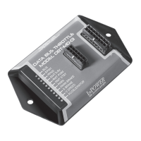
InPower’s DBT-MDF20 Data Bus Throttle both decodes the vehicle data bus
to provide you with the signals you need and provides high idle engine RPM
and PTO control. This product is compatible with 2020+ Ford trucks and vans
equipped with the Ford Stationary Elevated Idle Control (SEIC).
Modules come with four modes of high idle control: one standby mode, two
preset RPM modes, and one variable input RPM mode based on a customer-
supplied remote variable resistor. The standard module also includes four data
bus signal outputs: Park Brake Set, Reverse, Engine Run and Park (note: on
F750 chassis, the output is Neutral) with the capability of additional or alternate
outputs per customer special request. InPower Contact information is located
on the back page of this manual.
Note: The data bus signal outputs will continue to function so long as
the unit has power and vehicle ignition is in the run position. However,
the throttle functions will only operate if the Chassis Ready Conditions
are satised. LED diagnostic indicators are provided to aid in system
troubleshooting. These LEDs are located on the module opposite the
connectors.
Chassis Ready Conditions typically could be:
• No vehicle speed
• Accelerator not depressed
• Engine up to Operating Temperature
• Service brake not depressed
• Engine running and below 1,000 RPM
• No Diagnostic Trouble Code (DTC). Check Engine light must be off.
• Other hindering conditions will be detailed in the Body Builder’s Guide
(www.eet.ford.com/truckbbas/)
The DBT-MDF20 kit includes two cables. The rst cable (J1 Harness) connects
to the module via connector J1 and has three labeled sets of 20-inch blunt
cut wires: ve wires for SEIC, ve wires for inputs, and six wires for data bus
signal outputs. The second cable (J2 Harness) connects to the module via
connector J2 and has a 24 Pin SDLC Gateway connector and a set of seven
blunt cut wires for remote high idle control and preset RPM adjustments. This
Y-harness goes in place of the SDLC Gateway Plug where it plugs into the
back of the SDLC Gateway (See Section 2.4). Likewise the SDLC Gateway
Plug that plugged into the Gateway now should plug into the other connector in
the SDLC Gateway T-Harness.
Note: Ford vehicle wire colors and locations may vary substantially
between different models and even different model years. Please obtain
and consult the SEIC information for your specic vehicle prior to
installing the module. Documentation may be obtained from Ford’s
Truck Body Builder Advisory Service:
www.eet.ford.com/truckbbas/
 Loading...