DBT-MDF20 Owner’s Manual
Document: OM-232 Version Code:
Date: Jan 24, 2020 Date:
© Copyright 2020 InPower LLC
Page
7 of 14
InPower LLC
8311 Green Meadows Drive
Lewis Center, Ohio 43035 USA
740-548-0965
www.InPowerLLC.com
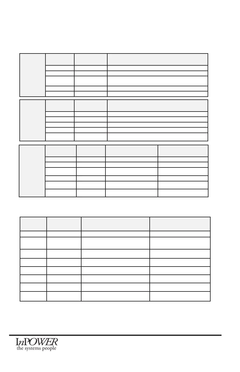
J1 Harness
Group 1
SEIC
Wire
Color
Connector
Pin #
Description
White 2 Input from PTO Relay/PTO
Brown 8 Input from PTO VREF
Orange 13 Output to PTO-REQ2 (Not Used - Do not Connect!)
Except used on Older Gas
Yellow 14 Output to PTO-REQ1
Green 16 Output to PTO-RPM
Group 2
Inputs
Wire
Color
Connector
Pin #
Function
Brown 3 Not Used (Low2)
Pink 4 Input RPM1 (High1) Overrides RPM2, RPM STBY, RPM Remote
Tan 5 Input RPM2 (High2) Overrides STBY and Remote RPM
Violet 6 Input RPM STBY (High3) Lowest Priority
Dark Blue 7 Input RPM Remote (High4) Overrides RPM STBY
Group 3
Outputs
Wire Color Connector
Pin #
Function Signal Output Level
Dark Green 1 Park Brake Set Ground (Out Low2)
Pink 9 Not Used Not Used (Out High 6)
Tan 10 Veh. In Reverse Positive (Out High 6)
Violet 11 Engine Run Positive (Out High 6)
Dark Blue 12 Park (750: Neutral) Positive (Out High 6)
Gray 15 Not Used Ground (Out Low 1)
J2 Harness
Wire
Color
Connector
Pin #
Function Comments
Black 1 Ground Gateway Connector
Black 2 Ground Out to Remote Accelera-
tor Control
Blunt Cut *
Orange 3 Input From 0-5V (T1)
Blunt Cut *
Red 7 +12V Power Input Blunt Cut
Violet 8 Not Used (VAux) Blunt Cut
Gray 9 RPM Adjust Blunt Cut
Pink 10 Input (T2) Not Used Blunt Cut
White 11 5V Output to Remote
Blunt Cut *
2.6 Harness Wires
* These three wires are for use with remote variable RPM
Note: J2 gray wire may be used to adjust calibration for all RPM settings (See section 2.5)
 Loading...