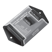
DBT-MDF20 Owner’s Manual
Document: OM-232 Version Code:
Date: Jan 24, 2020 Date:
© Copyright 2020 InPower LLC
Page
6 of 14
InPower LLC
8311 Green Meadows Drive
Lewis Center, Ohio 43035 USA
740-548-0965
www.InPowerLLC.com
D. Decoded Data Bus Signal outputs
Note: As long as the unit has power (connected via the Red wire on the J2
harness) and the vehicle is on (data bus signals are not transmitted when the
vehicle is off), the DBT-MDF20 will provide these output signals, regardless of
the status of the throttle controls and engine RPM.
All decoded signal output wires are located in the J1 harness in the bundle
marked Group 3 Outputs. Each wire corresponds to a different signal and all
wires give a 600mA current when connected. (Note: The pink wire and the
gray wire are unused in the standard model but may be given a custom signal
at customer request.) Tape or otherwise properly secure any unused wires
out.
Please see Section 2.6 for chart.
2.5 Adjusting Values of RPM settings
All four RPM modes (RPM1, RPM2, RPM Remote Variable, and RPM
Standby) come with Factory Calibrations but may be adjusted by the user if
so desired once the module is installed.
1. Activate the mode desired for adjustment by connecting the
corresponding line (Input RPM1, RPM2, RPM Remote, or RPM Stdby)
to +12V. Note: If the Remote Variable Accelerator RPM mode is
activated (Connector Pin 7 - Dark Blue), this process will adjust the
Maximum RPM setting.
2. Locate the grey wire (Pin 9) in the J2 harness. Apply +12V to this wire
to raise the RPM or ground the wire to lower it to the desired RPM.
For each second that +12V is connected to the RPM Adjust wire (Pin
9), the RPM will increase by 50 RPM per second. Likewise, if the
RPM Adjust wire is tied to GND, the RPM will decrease at a rate of 50
RPM per second. Releasing it from either +12V or Ground will steady
the RPM.
For each bump of less than a half second, the RPM will move by 25RPM up or
down (depending on whether Adjust is bumped to +12V or GND). If connected
to +12V or GND for a second (or more) it will increase by 50RPM for each
second the Adjust is connected to the voltage.
3. To permanently store the changed RPM, disconnect from all Input
RPM Mode lines but maintain power to the unit (powered by the
Ignition Key Switch). If you disconnect the power without rst
deactivating all modes, it will not store the changed values.
Note 1: An alternative to disconnecting the RPM Mode selection lines is to
simply trip one of the interlocks, for example, stepping on the Service Brake
(or Accelerator) for 10 Seconds will trip that interlock and store the value. For
the rst 5 seconds of the Interlock tripping, the associated LED will Flash and
shut down the Throttle Controller (storing the new RPM value). After that, the
Controller will restart, and it will re-read all the inputs (including Data Bus) and
update the state of the Controller based on all it’s inputs.
Note 2: A minimum of 910 RPM is recommended for PTO to activate, so we do
not recommend lowering the Standby RPM.
 Loading...