DBT-MDF20 Owner’s Manual
Document: OM-232 Version Code:
Date: Jan 24, 2020 Date:
© Copyright 2020 InPower LLC
Page
5 of 14
InPower LLC
8311 Green Meadows Drive
Lewis Center, Ohio 43035 USA
740-548-0965
www.InPowerLLC.com
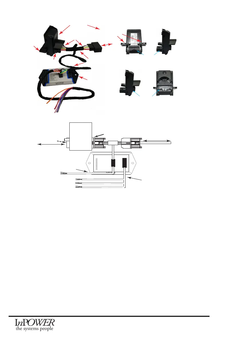
Side Back
SDLC
Gateway
Connector
Front Side
Secure
OBDII Con-
nector
Under Dash
Mounting
SDLC Ford Gateway
DBT-MDF20 SDLC
Harness
DBT-MDF20
Y Part of Harness
Secure OBDII
Connector
Harness SDLC
Gateway Connector
SDLC Gateway
Connector
To Chassis
P1
P2
DBT-MDF20 SDLC
Throttle Harness
J1
P2
J1
J2
www.InPowerLLC.com
Made in the USA
LOT: 1234567890
Diagnostic
LEDs
- Bus
- RPM1
- RPM2
- RMT 0-5V
- RMT PWM
- RPM STBY
- PARK
- PARK BRAKE
- S BRAKE
- V SPEED
- ACCELERATOR
DATA BUS THROTTLE
MODEL DBT-MDF20
Chassis Data Bus
Group 1 SEIC
Group 2 Inputs
Group 3 Outputs
DBT-MD I/O Harness
P1
J2
P3
RPM Adj, Remote
RPM/PWM, etc
Secure Data
OBDII
Connector
Ford
SDLC
Gateway
Chassis Data Buses
Connector
B. SEIC
Locate the Group 1 SEIC of blunt cut wires on the J1 harness. Install wires
between the blunt cut wires provided on the J1 harness and the respective
inputs and outputs of the Ford SEIC as shown in the wiring diagrams.
C. High Idle Mode Selection Controls
Determine the combination of high idle speed modes needed (standby high
idle, variable RPM control and/or up to two additional xed preset speeds).
The customer needs to supply a switch (or switches) for turning for selecting
the RPM1 and/or RPM2 modes, and for the Remote variable RPM, needs
to provide a 0 to 5V potentiometer. We recommend a three to ten-turn
potentiometer such as those found at Digikey and other similar vendors.
Alternatively this could be a 0-5V Accelerator Pedal.
Please refer to Section 2.6 for a complete chart of input and output wires. All
mode selection switches should be wired to the INPUTS wire group in the J1
Harness. The variable remote accelerator or potentiometer (if used) should be
wired to the appropriate wires in the J2 Harness.
 Loading...