DBT-MDF20 Owner’s Manual
Document: OM-232 Version Code:
Date: Jan 24, 2020 Date:
© Copyright 2020 InPower LLC
Page
4 of 14
InPower LLC
8311 Green Meadows Drive
Lewis Center, Ohio 43035 USA
740-548-0965
www.InPowerLLC.com
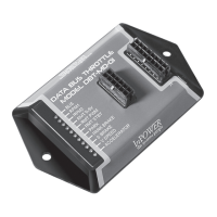
2.3 Mounting
Mount the DBT-MDF20 module under the dash or on a at surface using the
two mounting holes. Ensure that you have sufcient distance to install the 36
inch SDLC Gateway Y cable that is part of the J2 harness.
Plug the J1 cable into the J1 connector (16 pin connector) and plug the J2
cable into the J2 connector (12 pin connector). The J2 cable will be used
for the SDLC Y Gateway Connector, power input, and the remote RPM
potenitometer (Accelerator) adjustment. The J1 cable will be used for
hooking into the SEIC circuit, high idle on/off or mode select switches and for
providing output signals.
2.4 Wiring
Ensure the J1 cable and the J2 cables are both connected to the module.
Note: If the vehicle is on and the unit has power, even if the Preset RPM
functions are not engaged, the Databus Decoder signals will continue to
operate. If the Databus Decoder signals will not be used, properly secure
the Output wire group on the J1 harness.
A. Connecting the DBT-MDF20 to the Chassis
The Ford SDLC Gateway is the device which now provides the OBDII port for
the customer, and is located in the same location as the conventional location
for the OBDII port (Driver’s side (Left)) under the Dash. The SDLC Y Harness
Plug inserts into the SDLC Gateway connector on the back side of the Ford
SDLC Gateway. The Ford SDLC Gateway provides security for data requests
from the Secure Data OBDII data bus connection to the outside world.
To connect the DBT-MDF20 to the system, unplug the SDLC Gateway to
Chassis connector from the back of the SDLC Gateway, and Plug P2 of the
DBT-MDF20 SDLC Y-Harness into the Gateway where the Gateway cable
connector was previously. Then connect the Gateway to Chassis Connector
into P1 connector. This will provide access to Chassis GND and Chassis
Data.
 Loading...