The G4 Twin is a sophisticated graphic engine monitor designed to provide pilots with comprehensive, real-time data on their aircraft's engine performance. It aims to simplify complex engine monitoring into an intuitive, easy-to-understand format, enhancing flight safety and operational efficiency. The device is particularly useful for twin-engine aircraft, offering distinct monitoring capabilities for both left and right engines.
Function Description:
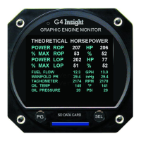
The primary function of the G4 Twin is to display critical engine parameters graphically, allowing for quick interpretation of engine health and performance. It monitors a wide array of data points, including:
- Buss Voltage: Provides an indication of the aircraft's electrical system voltage.
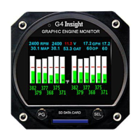
- RPM Indication L-R: Displays the revolutions per minute for both the left and right engines.
- Manifold Pressure L-R: Shows the manifold pressure for each engine, crucial for power setting.
- Fuel Flow L-R: Indicates the fuel consumption rate for both engines in gallons per hour (GPH).
- Oil Pressure L-R: Monitors the oil pressure for each engine, vital for lubrication system health.
- Outside Air Temperature (OAT): Displays the ambient air temperature, which affects engine performance and leaning.
- CHT Redline: Shows the maximum allowable Cylinder Head Temperature (CHT).
- CHT Graphic Bar: Provides a visual representation of CHT for each cylinder, with color coding (yellow at 410°F, red at 460°F) to indicate temperature ranges.
- EGT Graphic Bar: Displays Exhaust Gas Temperature (EGT) for each cylinder, also graphically.
- TIT Bars: Monitors Turbine Inlet Temperature (TIT) for both engines, with color coding (yellow at 1600°F, red at 1650°F) to highlight critical temperatures.
- EGT Peak: Indicates the peak EGT for each cylinder during leaning procedures.
- CHT Numeric Indication: Provides precise numeric values for Cylinder Head Temperatures.
- TIT Numeric Indication: Displays exact numeric values for Turbine Inlet Temperatures.
- Cylinder Number: Clearly labels each cylinder for easy identification.
- EGT Numeric Indication: Shows precise numeric values for Exhaust Gas Temperatures.
- EGT Lean of Peak (LOP) / Rich of Peak (ROP) Threshold: Assists in precise leaning by indicating when cylinders are operating lean or rich of peak EGT.
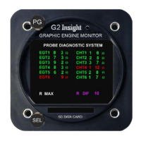
- Probe Diagnostic System: A crucial feature for pre-flight checks, this system assesses the health of all engine probes (EGT, CHT, TIT, OILT) for both engines. It displays resistance values for each probe and uses color coding (green for good, red for a problem) to quickly identify any issues. This allows pilots to detect probe malfunctions on the ground, preventing potential issues during flight.
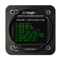
- Fuel Setup and Totalization: Manages fuel data, including last onboard quantity, fuel added, subtotal, fuel used, and current fuel remaining. It also calculates endurance and fuel rate, providing a comprehensive overview of fuel management.
- EGT Variation Cylinder Analysis (EVA): This advanced feature continuously analyzes EGT variations across all cylinders. It presents the data graphically, showing a flat line with a little noise for normal operation and distinct spectral peaks for cylinders with potential issues, particularly related to exhaust valve degradation. This is a predictive maintenance tool designed to forewarn pilots of pending engine problems.
Usage Features:
The G4 Twin is designed for intuitive interaction through two control knobs:
- PG (Page) Knob: Generally controls screen selection, allowing pilots to navigate between different monitoring pages (e.g., main engine display, probe diagnostics, fuel management, EGT variation).
- SEL (Select) Knob: Controls items within the currently displayed screen. Its function adapts to the context of the screen. For example:
- Engine Selection: Spinning the SEL knob to the right selects the right engine's data, while spinning it to the left selects the left engine's data. Pushing and holding the SEL knob allows switching to a twin-engine overview page.
- EGT Bar Height Adjustment: On the main engine display, pressing the SEL knob once allows pilots to rotate it to adjust the height of the EGT bars for better visibility.
- Leaning Target Adjustment: Pressing the SEL knob a second time enables adjustment of the leaning target (e.g., 50°F below peak EGT).
- Saving Adjustments: Pressing the SEL knob a third time saves any adjustments made to EGT bar height or leaning targets.
- Lean Mode Activation: Pressing and holding the SEL button activates the special lean mode functions, which assist in precisely leaning the engine.
- Fuel Management: On the FUEL TOTALIZATION screen, pressing the PG button allows entering fuel data. The SEL knob can be used to top up tanks by turning it counter-clockwise on the first click.
- EGT Variation Analysis: When large spikes appear on the EGT Variation screen, the SEL knob can be used to dial in and view data for a specific cylinder, helping to pinpoint the source of a problem.
The device's graphical interface, with its color-coded bars and numeric readouts, simplifies the interpretation of complex engine data. The "lean mode" provides real-time feedback on EGT drops from peak, indicating whether the engine is operating rich or lean of peak, and records the fuel flow at peak EGT for each cylinder. This is crucial for optimizing fuel efficiency and engine longevity.
Maintenance Features:
The G4 Twin incorporates features that aid in proactive maintenance and troubleshooting:
- Probe Diagnostic System: This pre-flight check feature is a key maintenance tool. By identifying faulty probes (indicated by red on the display) before flight, it helps prevent in-flight data inaccuracies and allows for timely replacement of sensors. This is particularly important as probe issues can mask underlying engine problems or provide misleading information.
- Exhaust Valve Analysis (EVA): This is a significant predictive maintenance feature. By continuously monitoring and analyzing EGT variations, the G4 Twin can detect early signs of exhaust valve degradation, a leading cause of catastrophic engine failure. The display of spectral peaks on the EGT Variation screen serves as an early warning, giving pilots and maintenance personnel ample time to investigate and address potential valve issues before they become critical. A "flat line with a little noise" indicates normal operation, while a "trouble indication will show as an obvious spectral peak" signals a problem. This allows for scheduled maintenance rather than reactive repairs, improving safety and reducing downtime.
- Context-Sensitive Controls: The device's ability to label controls with guidance information like "Push to exit" or "Turn to adjust" simplifies operation and reduces the learning curve, ensuring that pilots can effectively utilize all maintenance-related features without extensive training.
The G4 Twin's design emphasizes early detection and clear communication of engine health, transforming complex engine data into actionable insights for pilots and maintenance teams. Its focus on graphical representation, intuitive controls, and predictive analysis makes it an indispensable tool for safe and efficient aircraft operation.