Pg. 10 V12192022_CG3.1PK
STEP 2
A. Install the Guide Rods (7) into the holes of the bottom Right Main Frame (1) tubes, using two M10 x 80 Allen Bolt
(41) and two M10 Washers (26) insert through the bottom tubes and holes in the guide rods, then into the internal
threads of the tube.
B. Lubricate the Guide Rods with Lube (43) provided.
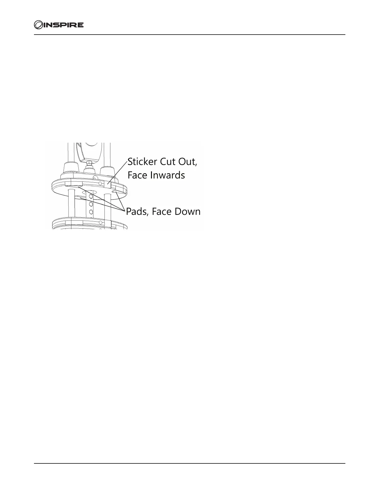
C. Install two Risers (31) and two Rubber Bumpers (37) on each Guide Rod (7) as shown. Slide ten 10lbs Weight
Plates (13) from the top of the Guide Rods (7), down to the Rubber Bumpers (37). Make sure the weight sticker cut
out is facing the inside of the machine and the protruding pads on the weights are facing downward.
D. Still working on the Right Main Frame (1). First, remove the two M10 x 20 Allen Bolts (14), M10 Lock Washers
(17) and Flat Washers (26), which were pre-assembled to hold the Guide Rod Bracket (6) and set it aside. Slide the
Top Plate Assembly (10) onto the Guide Rod (7). Next remove the Pulley (9) from the U-Shaped Pulley Bracket
(8), wrap the cable around the Pulley (9) then re-insert it into the U-Shaped Pulley Bracket (8) using the M10 x 50
Allen Bolt.
E. Slide the Guide Rod Bracket (6) back onto the Guide Rods (7). Place the Guide Rod Bracket (6) back up into the
Right Main Frame (1) and secure it using two M10 X 20 Allen Bolts (14), two Lock washers (17) and two M10
Washers (26).
F. Lower the Top Plate Assembly (10) down onto the top of the Weight Plate (13) stack.
G. Check all the cables to make sure they are on track on the pulleys.
H. Place provided Weight Stack Stickers (35) one on the Top Plate Assembly (10) rst and the rest in the cut out of
each Weight Plate in ascending order down from the top.
I. Insert Weight Selector Pin (12) into the Weight Plate (13) stack.
J. If needed, adjust the cable tension by rst loosening the M10 x 50 Allen bolt (33) on the Top Plate Assembly (10),
then rotate the M50 Tension Adjustment Plate (18) clockwise or counterclockwise to move the Pulley (9) up and
down. Once desired tension is achieved, securely tighten the Bolt.
K. Repeat all the steps above for the Left Main Frame (2).