10
STEP 2
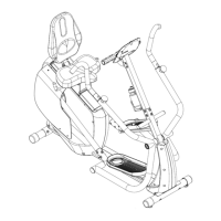
a) Assemble Backrest Assembly (#7) onto Seat Slider Assembly with qty 1 – M8x70 bolt (#9),
qty 1 – M8 washer (#3), and qty 1 – Locking Cap Nut (#2).
b) Choose a preferred Seatback Recline Angle (See Figure B). The Backrest Assembly (#7)
may be installed in 3 different recline angles (FORWARD, MIDDLE, BACK) based on the
user’s preferred position. Align holes based on preferred seat position and place
Adjustment Pin (#5) through aligned holes.
c) Assemble Right Cam Lock Handle (#12) to Seat Slider Assembly and tighten the socket
screws (a). NOTE: ENSURE THAT THE RIGHT CAM LOCK HANDLE HAS AN
“R” STICKER.
d) Assemble Left Cam Lock Handle (#19) to Seat Slider Assembly and tighten the socket
screws (a). NOTE: ENSURE THAT THE LEFT CAM LOCK HANDLE HAS AN “L”
STICKER.
e) Assemble Seat Bottom Pad Assembly (#10) onto Seat Slider Assembly using qty 4 – M8
washers (#3) and qty 4 – M8 Cap Nuts (#18).