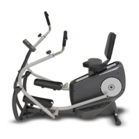
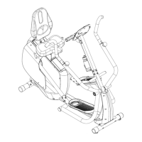
14
STEP 4
a) Place Swing Arm Assembly (#21) onto the right side U-Bracket of the Front Frame
Assembly (#43). Secure using qty 1 – Ø10x75mm Shoulder Bolt (#39), qty 1 – M8
Washer (#3), and qty 1 – M8 Locking Cap Nut (#2).
b) Assemble Swing Arm Assembly (#21) to Right Pedal Arm Assembly (#24) using qty 1 –
Ø10x85mm Shoulder Bolt (#30), qty 1 – M8 Washer (#3), and qty 1 – M8 Locking Cap Nut
(#2).
c) Place Swing Arm Assembly (#21) onto the left side U-Bracket of the Front Frame Assembly
(#43). Secure using qty 1 – Ø10x75mm Shoulder Bolt (#43), qty 1 – M8 Washer (#3), and
qty 1 – M8 Locking Cap Nut (#2).
d) Assemble Swing Arm Assembly (#21) to Left Pedal Arm Assembly (#27) using qty 1 –
Ø10x85mm Shoulder Bolt (#30), qty 1 – M8 Washer (#3), and qty 1 – M8 Locking Cap Nut
(#2).