FORCE/2 Wireless Retrot System
Operation Instructions
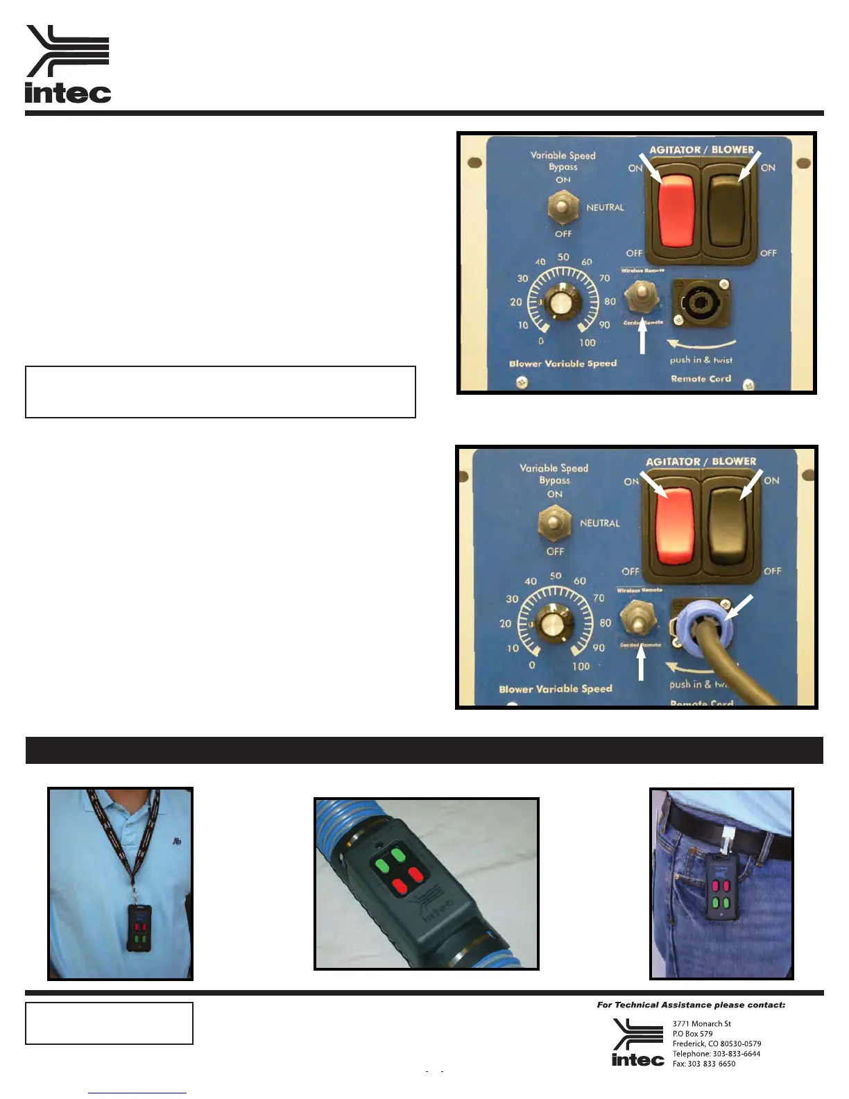
Wireless Remote Operation:
Rev: 08/10
Attach the transmitter to the blowing hose, belt clip or lanyard (see
wireless remote congurations at bottom of page). At the electrical
panel, locate the remote selector switch, position the switch to the
wireless remote position “Up” (Fig 1), once the remote bypass switch
is in the wireless remote position, depress the main control switches
(agitator & blower) to the “on” position (Fig 2 & 3). DO NOT PLUG
IN STANDARD REMOTE CORD WHEN USING WIRELESS
FEATURE. Depress the Green buttons on the wireless transmitter
to start the motors. NOTE: The main panel switches must be in the
“on” position for the machine to operate. The operator located at the
machine may stop either motor by pushing the switch to the “off”
position.
Remote Cord Operation:
Attach the remote cord to the electrical panel (Fig 4). At the electri-
cal panel, locate the remote selector switch, position the switch to the
remote cord position “Down” (Fig 5), once the remote selector switch
is in the remote cord position, depress the main control switches (agi-
tator & blower) to the “on” position (Fig 6 & 7). Depress the rocker
switch on the remote to start the motors. NOTE: The main panel
switches (Fig 6 & 7) must be in the “on” position for the machine to
operate. The operator located at the machine may stop either motor by
pushing the switch to the “off” position.
L
A
N
Y
A
R
D
HOSE ATTACHMENT
B
E
L
T
C
L
I
P
Wireless Remote Congurations
Fig 1
Fig 3
Fig 2
Fig 6 Fig 7
Fig 4
Fig 5
8-01-2010
Note: To preclude possible back ow of material going into the blower motor.
STARTING MACHINE, start the blower rst then the agitator. SHUTTING
MACHINE OFF, turn off the agitator then the blower.
Miscellaneous:
Transmitter battery: Qty 2, CR2450
Operation range: 250’
Doc: 21211
 Loading...