Effective 7/19/2010
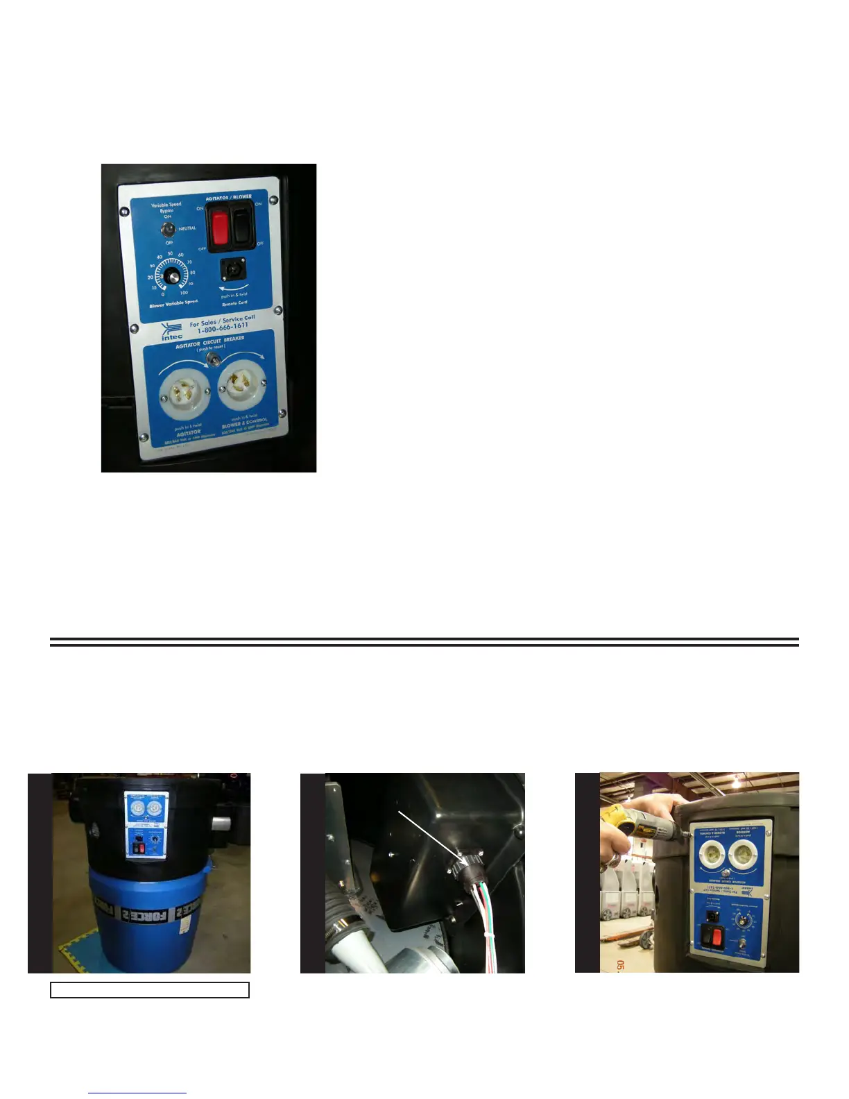
Note: This wireless kit will only t on
those machines manufactured after
4/2005, see lower left hand corner of
the electrical panel for date code.
Installation Instructions
Part Number 21200
(115VAC ONLY)
Approximate install time
(1-2 hours)
Tools Needed
Electric drill, 3/16, 3/8, & 1/2”drill bit, #2 Phillips screwdriver, center
punch, hammer, wire cutter/stripper, Qty (2) 7/16”, Qty (1) 5/8” and Qty
(1) 11/16”open end wrenches, pliers, rubbing alcohol, clean rag, Qty (2)
2 x 4 x 12” wood pieces and a small at le.
CAUTION!
BEFORE PERFORMING ANY WORK, MAKE SURE
THE FORCE/2 IS NOT PLUGGED INTO AN
ELECTRICAL OUTLET OR INJURY MAY OCCUR!
Turn the Force/2 upside down as
shown.
Locate the circular connector on
the side of the electrical box as
shown. To remove, turn outer ring
of connector, counter clockwise,
pull gently to remove.
Using a #2 Phillips screwdriver,
remove the six screws holding the
electrical face panel on the ma-
chine. When nished, set aside the
screws for use during re-assembly.
Outer ring
Note: Requires two people.
S
T
E
P
1
S
T
E
P
2
S
T
E
P
3