During removal of electrical box
and panel, make sure to support the
electrical box as shown.
Slide the electrical panel through
opening in base as shown. Once
you have successfully guided the
electrical panel though the hole,
remove electrical box and panel.
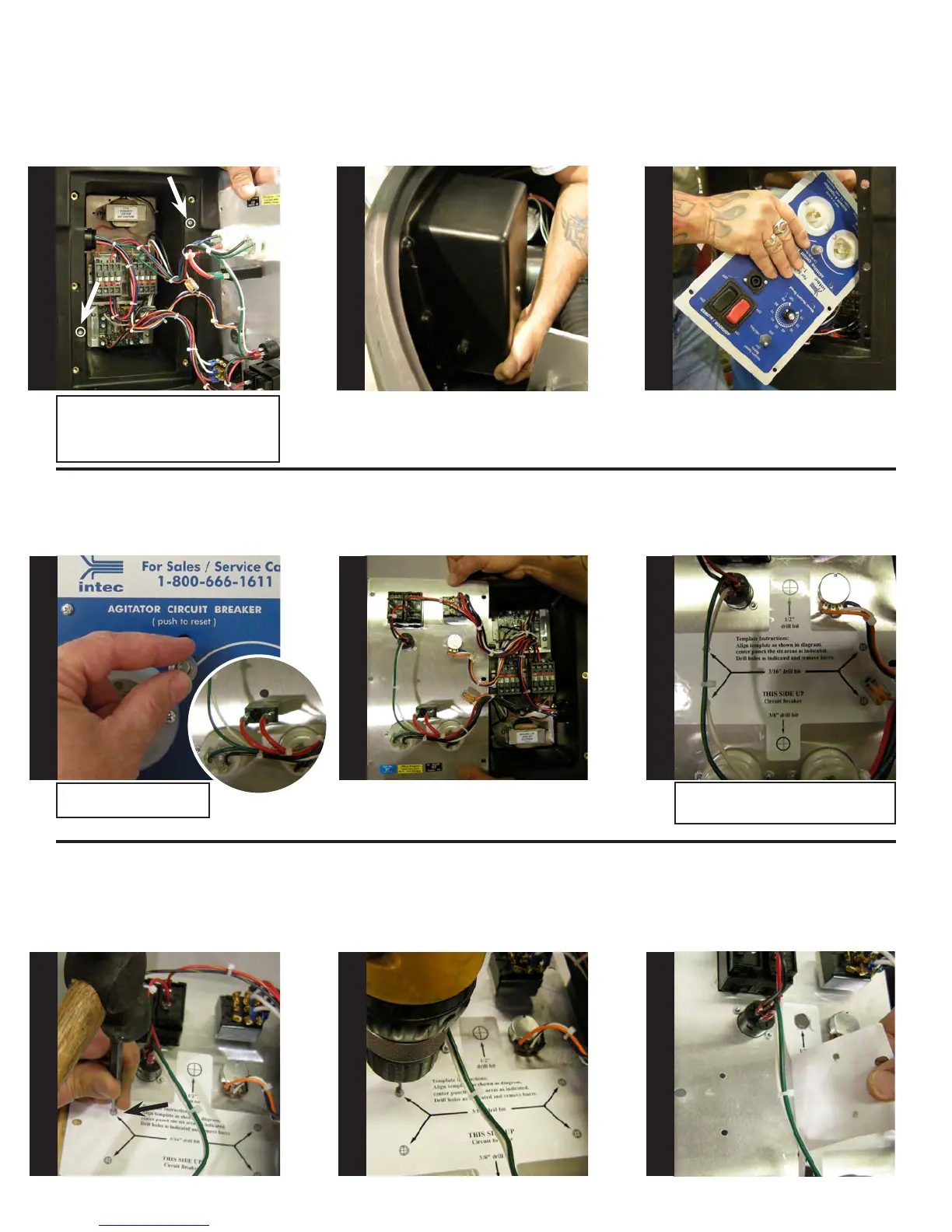
Remove the clear circuit breaker
seal by turning counter clockwise.
Push circuit breaker through the
panel and set aside.
Use alcohol to clean the back of the
control panel, allow to dry. Apply
drill template as shown.
Before center punching panel, place
a 2 x 4 underneath electrical panel
for support. Center punch all (6)
drill point areas.
Pilot drill all (6) center punched
areas using the 3/16” bit, then drill
holes as indicated on the template.
When nished, de-burr all drilled
holes, remove template and clean
out any metal shavings which may
have fallen into electrical box.
Place the electrical box with the
panel facing up, lift the control
panel up and ip it to the left.
Note: Make sure to support the electri-
cal box while removing the two mounting
screws. When nished, set screws aside
for use during re-assembly.
S
T
E
P
4
S
T
E
P
5
S
T
E
P
6
S
T
E
P
7
S
T
E
P
8
S
T
E
P
9
S
T
E
P
10
S
T
E
P
11
S
T
E
P
12
Note: Circuit breaker shown
from back of electrical panel.
Hint: Use the two mounting holes
for alignment.
Carefully remove the electrical
panel as shown. Caution:Do not
pull on the wires! Using a #2 Phil-
lips screwdriver, remove the two
screws holding the electrical box,
see arrows.