Use alcohol to clean outside of
electrical box, allow to dry before
applying template as shown.
Drill pilot hole using 3/16” drill bit.
Next, drill out pilot hole using 1/2”
drill bit.
At this point, all holes should be
drilled in the electrical face plate,
as shown.
Re-install both circuit breaker and
seal into newly drilled hole in elec-
trical face plate, as shown. Install
the plastic plug into the original
circuit breaker hole. CAUTION: Do
not over tighten, hand tighten only!
At this point, all holes should be
drilled.The circuit breaker and plug
should also be installed
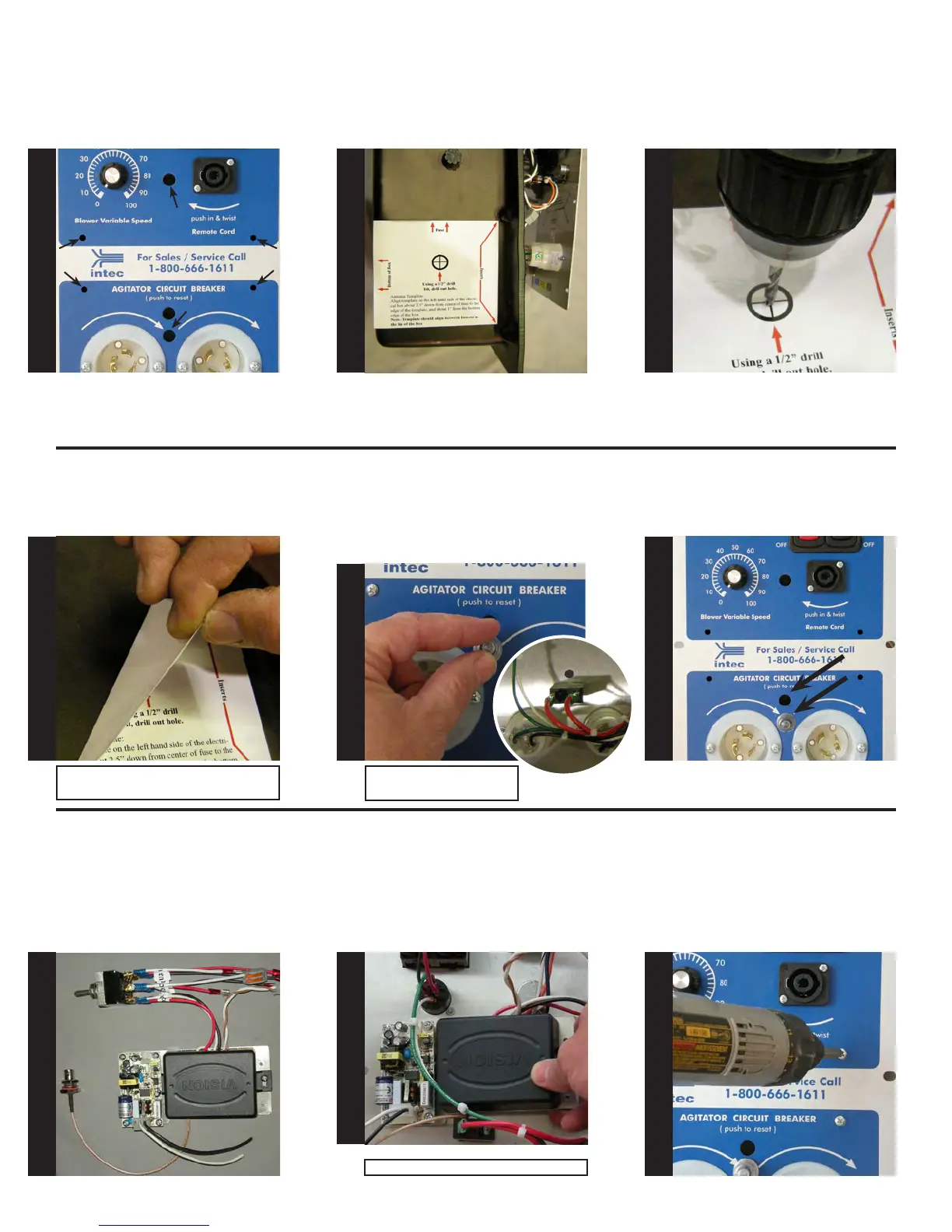
Next, locate the wireless receiver,
remote selector switch and antenna
mount as shown.
Front view of electrical panel: Se-
curing wireless receiver to electri-
cal panel.
Remove template and clean shav-
ings from electrical box and set
aside.
Note: If compressed air is available, blow
out all shavings.
Mount the wireless receiver to the
back of the electrical panel by slid-
ing the device underneath the wires
as shown. Secure wireless receiver
to the electrical panel by using a #2
Phillips screwdriver and the four
6-32 x 1/4” screws.
Note: do not over tighten.
S
T
E
P
13
S
T
E
P
14
S
T
E
P
15
S
T
E
P
16
S
T
E
P
17
S
T
E
P
18
S
T
E
P
19
S
T
E
P
20
S
T
E
P
21
Note: Circuit breaker shown
from back of electrical panel.