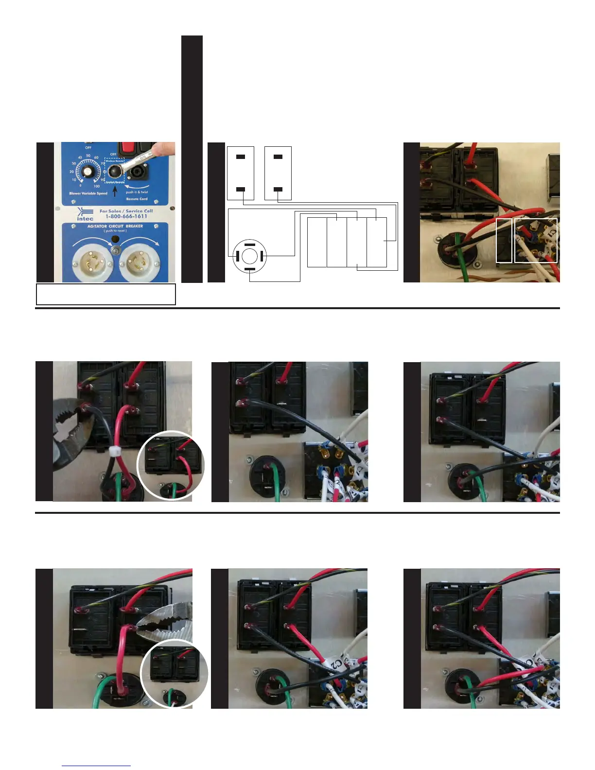
Install Remote Selector Switch
sticker over hole as shown and
mount Remote Selector Switch.
Secure switch using Toggle Switch
Seal. Tighten switch using a 5/8”
wrench and hold the back of the
switch to prevent rotation.
Using pliers, remove and discard
the black wire going from rocker
switch 1(Terminal 4) and remote
quick disconnect (Terminal 2+).
Locate the wire marked (C1) on the
remote selector switch and connect
it to rocker switch 1 (Terminal 4).
Locate the wire marked (U1) on the
remote selector switch and con-
nect it to, remote quick disconnect
(Terminal 2+).
Remove and discard the red wire
going from rocker switch 2, (termi-
nal 4) and remote quick disconnect
(Terminal 1+).
Locate the wire marked (C2) on the
remote selector switch and connect
it to, rocker switch 2 (Terminal 4).
Locate the wire marked (U2) on the
remote selector switch and con-
nect it to, remote quick disconnect
(terminal 1+).
The black wires at this point should
be on the right hand side of the
switch and the blank area on the
left, see below for details.
Selector
switch
S
T
E
P
22
S
T
E
P
25
S
T
E
P
26
S
T
E
P
27
S
T
E
P
28
S
T
E
P
29
S
T
E
P
30
S
T
E
P
24
Blank area
Wiring Section
Wiring diagram: Rocker switch 1 & 2,
Remote Quick Disconnect and Remote
Selector Switch.
Reference
Only
Remote
Selector
Switch
U3
C3
D3
U2
C2
D2
U1
C1
D1
Rocker
Switch 1
Rocker
Switch 2
Remote Quick
Disconnect
2+
1+
2-
1-
2
4
2
4
Black
Red
Black
White
Red
S
T
E
P
23
Label
2
4
2
4
2
4
2
4
2
4
2
4
2
4
2
4
2
4
2
4
2
4
2
4
2
4
2
4
Note: Make sure to secure the toggle
switch with the seal.