Locate and disconnect the white
wire on the Remote Quick Discon-
nect (terminal 1-).
Locate the wire marked (U3) on the
remote selector switch and con-
nect it to remote quick disconnect
(terminal 1+).
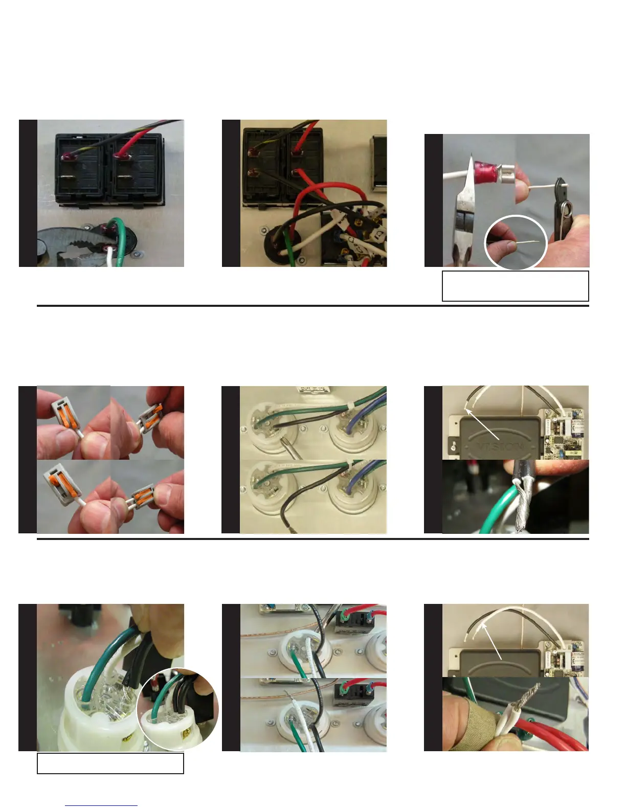
Locate the white wire which was
removed in step 31. Using wire
cutters, cut off existing terminal
as shown. Using wire strippers,
strip the white wire back, 3/4”, see
photo. Next, attach the stripped
wire to the Wago terminal on C3
from the remote selector switch.
Locate the anged inlet for the
blower. Using a #2 Phillips screw-
driver, remove the black wire as
shown in picture 5 & 6
Locate the black wire on the wire-
less remote receiver. Twist together
the black wire from the anged
inlet and wireless remote receiver,
see picture 7 & 8.
Insert twisted wires into anged
inlet as shown. Using a #2 Phillips
tighten screw and verify the wires
are secure by gently pulling on
them.
Pic 5
BLACK WIRE
REMOVED
Pic 6
BLACK WIRE
Pic 7
Pic 8
Pic 1
Pic 3
Pic 2
Pic 4
WHITE WIRE
Pic 11
Pic 12
Locate the blower anged inlet.
Using a #2 Phillips screwdriver,
remove the white wire as shown.
See Picture 9 & 10
Locate the white wire on the wire-
less remote receiver. Twist together
the white wire from the anged
inlet and wireless remote receiver,
see picture 3 & 4.
Pic 9
Pic 10
WHITE WIRE
REMOVED
Note: Do not nick or cut off the wires!
Also, to achieve a good t you may need to
trim off excess wire.
Connecting Wago terminal on C3
Pic 1 = Opening connector
Pic 2 = Open, ready for wire
Pic 3 = Insert wire
Pic 4 = Close connector
Test pull wire connection
S
T
E
P
31
S
T
E
P
32
S
T
E
P
33
S
T
E
P
34
S
T
E
P
35
S
T
E
P
36
S
T
E
P
37
S
T
E
P
38
S
T
E
P
39
Note: May have to rotate circuit breaker to
tighten screw on ange.