Page 13 of 37 Article no.: 1080621015 2022_01_18 Subject to technical change! Errors excepted.
- Instruments which have been replaced or exchanged must be disposed of according to relevant
environmental regulations.
- The display is deactivated and can be activated for two minutes by pushing the button.
- Unit of energy and installation point (outlet flow / inlet flow) can be set on location, only once, before
start of operation by pushing the button or alternatively using the „Device Monitor“ software.
- Type and concentration of glycol in the medium of those mechanical meter types designed to be used
with glycol can be set on location at any time using the „Device Monitor“ software (see item 8.1 for
details).
3.1 Pictograms installation point
On the right in the meter display in all information loops you will find one of the following two pictograms. The
pictogram indicates in which pipe the meter is to be mounted.
Installation in outlet flow
Installation in inlet flow
3.2 Pictograms type of meter (on type identification label)
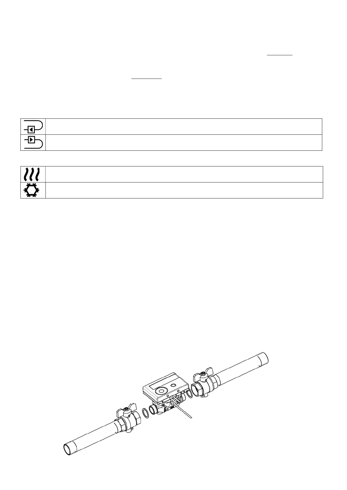
4 Mounting the Flow Sensor
4.1 Mounting of AMTRON
®
S3 / AMTRON
®
S3+ / AMTRON
®
S3U (measuring tube)
- Flush the pipes professionally, taking care not to damage any system components. Then close all the shut-
off valves.
- Open the nearest draining valve for pressure release.
- Drain the closed-off pipe section.
- Loosen the coupling rings and remove the old heat meter.
- Remove all old gaskets and clean the sealing surfaces. Insert new gaskets.
- Position the flow sensor correctly, taking into account the direction of flow (arrow on the side of the flow
sensor)!
- Tighten the coupling rings.
- Rotate the calculator to the best position for read-out, or detach it and mount it nearby.
Note concerning
AMTRON
®
S3U
: For the mounting in a heating system with a small quantity of air in the medium
we recommend to overturn the meter through 90°.
 Loading...