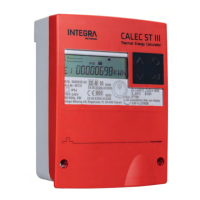
What to do if SYSt-Error appears on INTEGRA Metering CALEC ST III?
C
Christopher HaynesAug 4, 2025
If you are encountering a SYSt-Error with your INTEGRA Metering Measuring Instruments, it could be due to a component error, a device error, or the Analog-Digital-Converter not working correctly. In any of these cases, the suggested solution is to send the device in for inspection.
S
Stephanie LeeAug 17, 2025
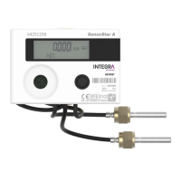
How to troubleshoot th-ERROR on INTEGRA Metering CALEC ST III?
J
John CruzAug 17, 2025
If you are seeing a 'th-ERROR' on your INTEGRA Metering Measuring Instruments, it could be due to several reasons. First, check the wiring to ensure the sensor is connected correctly. Second, use an ohm meter to check for interruptions or short circuits in the sensor cables of disconnected sensor wires. Finally, verify the input with a resistor: Pt 100 should read 100-150 ?, and Pt 500 should read 500-620 ?.