Installation
34 / 56
3-140-UM-EN-02
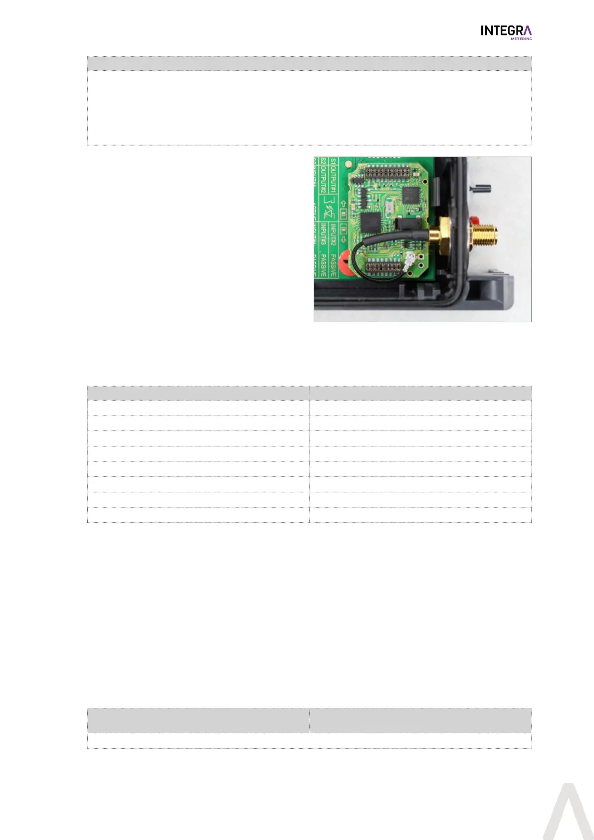
Module #2
Factory settings:
Frequency: 868MHz
Gain: 0db
Impedance: 50Ω
Antenna connector: SMA connector
u Disconnect the CALEC® ST III from the power
supply.
u Take off the front cover [}p.20].
u Connect the antenna (0db gain, 50Ω imped-
ance) to the SMA socket.
u Tighten the antenna with max. 5Nm.
u Close the front cover [}p.20].
u Place the device at the position with the best re-
ception.
u Supply voltage.
Analog output
CALEC® ST III can be equipped with up to four passive analogue outputs. An external power supply is re-
quired for operating purposes. The current per channel can be adjusted within a range of 0–20mA or 4–
20mA. The following readings can be emitted as current signals:
Factor Display
Temperature on “hot” side t-hot
Temperature on “cold” side t-cold
Temperature on difference t-diff
Output POUEr
Flow FLOU
Mass flow MAS-FLOU
C-factor C-Factor
Density dEnSitY
Limit-value signals
Digital output signals can be used to emit limit-value monitoring signals.
l Function of one-sided limit-value monitoring (Limit1)
If an adjustable maximum limit is exceeded or if the reading fails to reach an adjustable minimum, the out-
put signal switches over, hysteresis (0 - 10 %) and control direction are selectable as required. While the ex-
cess-reading remains in force, the meter (showing “Cnt” for “counter”) calculates the total duration of the
error for inspection purposes.
l Function of two-sided limit-value monitoring (Limit2)
If an adjustable maximum limit is exceeded and if there is failure to reach an adjustable minimum, the func-
tions operate in a similar way to those of Limit1.
l Alarm message
l The microprocessor monitors the temperature sensor and internal functions, and displays any resulting
error messages. This information can also be used to generate an alarm signal via the digital outputs.
Module #1: A11/B11 (Channel #1)
Module #1: A12/B12 (Channel #2)
Module #2: A21/B21 (Channel #1)
Module #2: A22/B22 (Channel #2)
The outputs are electrically isolated.
 Loading...