Installation
3-140-UM-EN-02
31 / 56
5.3.12 Connecting the communication modules
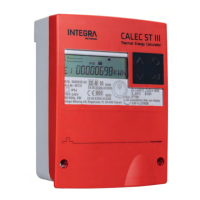
M-Bus
Additional M-Bus modules can be inserted in the CALEC® STIII in order to duplicate network or to manage
several data flow for different solutions.
Module #1: A11/B11 (Channel #1) Module #2: A21/B21 (Channel #1)
Analogue outputs are electrically isolated
The use of primary and secondary addresses is possible
Setting the baud rate is possible
Factory settings:
Primary address: 0
Secondary address: serial number
Baud rate: 2’400 Baud
u Disconnect the CALEC® STIII from the power
supply.
u Take off the front cover [}p.20].
u If module #1 is installed: Connect the M-Bus to
terminals A11 and B11.
u If module #2 is installed: Connect the M-Bus to
terminals A21 and B21.
u Close the front cover [}p.20].
u Apply voltage.
For the programming options to this module see M-
Bus [}p.45].
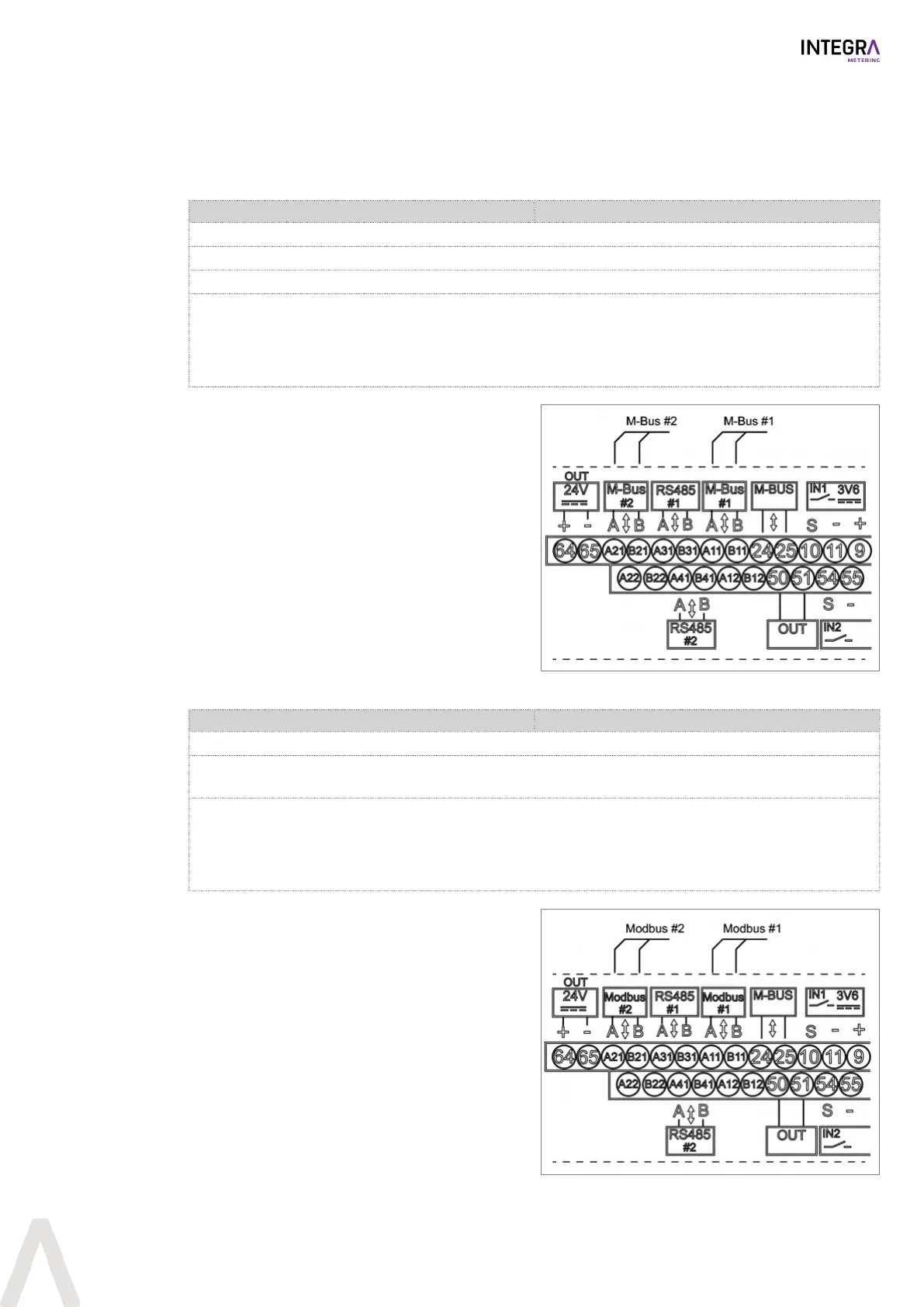
Modbus RTU
Module #1: A11/B11 (Channel #1) Module #2: A21/B21 (Channel #1)
The interface is electrically isolated.
When installing CALEC® ST III at the end of the Modbus segment the internal termination resistor can be
used.
Factory settings:
Modbus address: 1
Parity: Even
Baud rate: 19’200 Baud
u Disconnect the CALEC® STIII from the power
supply.
u Take off the front cover [}p.20].
u If module #1 is installed: Connect the Modbus to
terminals A11(+) and B11(-).
u If module #2 is installed: Connect the Modbus
to terminals A21(+) and B21(-).
u Close the front cover [}p.20].
u Apply voltage.
For the programming options to this module see
Modbus [}p.45].
 Loading...