Installation
3-140-UM-EN-02
25 / 56
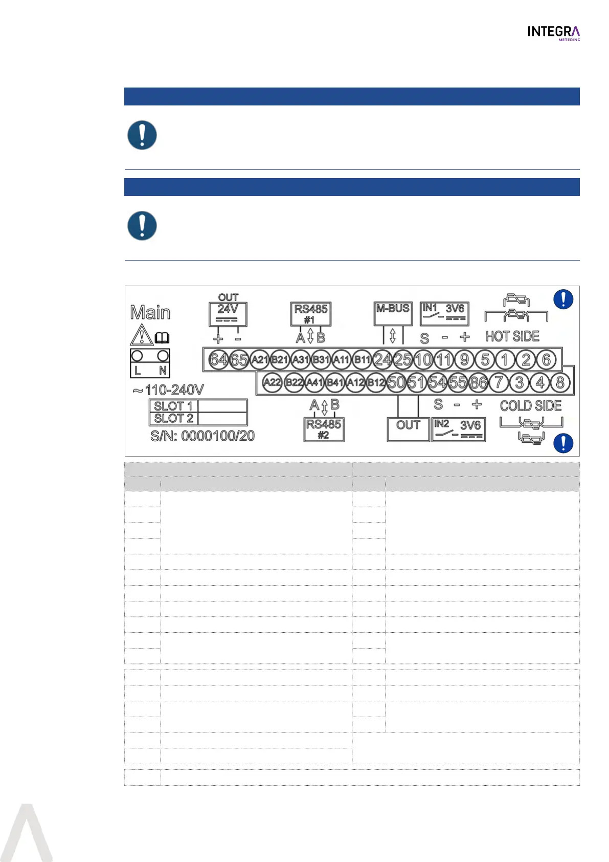
5.3.2 Connecting the CALEC® STIII Smart
NOTICE
Wrong connections may destroy the device
The function and the marking of the terminals A11/B11, A12/B12, A31/B31, A41/B41, A21/B21,
A22/B22 depends on the options installed in the device.
u Carefully check the installed options and choose the correct connections.
NOTICE
Incomplete wiring of the temperature sensors
Incomplete wiring of the 2-wire temperature sensors may lead to false measurement results.
u Always connect the 2-wire temperature sensors together with the four supplied wire
bridges.
u Connect the meter according to schematic diagram on the inside of the front cover.
Upper row Lower row
Label Function Label Function
6
Temperature
Hot side (2/4 wires)
8
Temperature
Cold side (2/4 wires)
2 4
1 3
5 7
9 Sensor power +3.6V 86 Sensor power +3.6V
11 GND #1 55 GND #2
10 Pulse input #1 54 Pulse input #2
25 M-Bus B 51 Digital out A
24 M-Bus A 50 Digital out A
B11
Socket #1
Channel 1
B12
Socket #1
Channel 2
A11 A12
B31 RS485 #1 B B41 RS485 #2 B
A31 RS485 #1 A A41 RS485 #2 A
B21
Socket #2
Channel 1
B22
Socket #2
Channel 2
A21 A22
65 Sensor power -24V
64 Sensor power +24V
L, N Main power supply
 Loading...