Installation
3-140-UM-EN-02
35 / 56
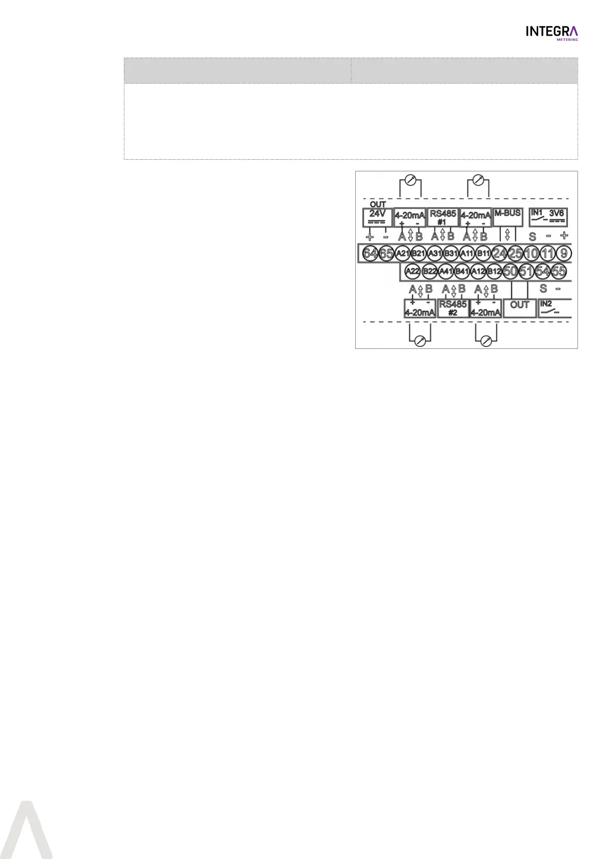
Module #1: A11/B11 (Channel #1)
Module #1: A12/B12 (Channel #2)
Module #2: A21/B21 (Channel #1)
Module #2: A22/B22 (Channel #2)
Module specifications:
Current range: 4…20mA / 0…20mA
Supply voltage: 6…24VDC
Electronical isolation max.: 48VDC
Resistance ≤ 837Ω / 24VDC
u Disconnect the CALEC® ST III from the power
supply.
u Take off the front cover [}p.20].
u If module #1 / channel1 is used:
Connect the passive analog signals to terminal
A11 (+) and B11 (-).
u If module #1 / channel2 is used:
Connect the passive analog signals to terminal
A12 (+) and B12 (-).
u If module #2 / channel1 is used:
Connect the passive analog signals to terminal
A21 (+) and B21 (-).
u If module #2 / channel2 is used:
Connect passive analog signals to terminal A22
(+) and B22 (-).
u Close the front cover [}p.20].
u Apply voltage.
For the programming options to this module see I-
Out [}p.44].
 Loading...