EasyManua.ls Logo

Integra Codman DirectLink - User Manual

Integra Codman DirectLink
7 pages
Print Icon
To Next Page IconTo Next Page
Loading...
For complete operating instructions, please refer to the manufacturer’s user manual
DirectLink® ICP Module
For the Direct Connection of the
Codman Microsensor
®
ICP Transducer
to a Patient Monitoring System
Reference Signal
Indicators
Status Lights
Arrow Buon
(Patient Monitor
Calibration)
Zero Buon
(ICP Sensor Zeroing)
Output Connection
(To Patient Monitor)
Input Connection
(To Extension Cable & ICP Sensor)
A DIVISION OF INTEGRA LIFESCIENCES integralife.com
QUICK REFERENCE GUIDE
Question and Answer IconNeed help?

Do you have a question about the Integra Codman DirectLink and is the answer not in the manual?

Summary

Patient Monitor Setup

Powering the ICP Module & Calibrating to the Patient Monitor

Connect the ICP Module to the patient monitor, wait for solid amber status light, then follow calibration steps using the arrow button.

ICP Sensor Setup

Zero the ICP Sensor Prior to Implantation

Connect ICP Extension Cable and Transducer to the module. Verify amber status, press and hold ZERO BUTTON until green light appears.

Disconnecting & Reconnecting

Patient Monitor for Transport and Patient Care Activities

Reconnect module and sensor to the same module used for zeroing. Press ARROW and ZERO buttons to confirm zero and continue monitoring.

Troubleshooting

SOLID RED LIGHT - MODULE ERROR DETECTED

Explains the reset procedure for a solid red light (disconnect/reconnect power) and troubleshooting steps for self-test and during use errors.

FLASHING AMBER LIGHT WILL NOT TURN GREEN

Discusses issues with non-stable signals during zeroing, sensor implantation, and resuming monitoring with the acknowledge function.

Overview

The DirectLink® ICP Module is a specialized device designed for the direct connection of the Codman Microsensor® ICP Transducer to a patient monitoring system, enabling the measurement of intracranial pressure (ICP). This quick reference guide provides essential information for its setup, calibration, and troubleshooting, ensuring accurate and reliable ICP monitoring.

Function Description

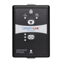
The primary function of the DirectLink® ICP Module is to act as an interface between the Codman Microsensor® ICP Transducer and a patient monitor. It processes the signal from the ICP transducer, converting it into a format that can be displayed and interpreted by standard patient monitoring systems. This allows healthcare professionals to continuously monitor a patient's ICP, which is crucial for managing various neurological conditions. The module features reference signal indicators for 0 mmHg and 100 mmHg, status lights, an arrow button for patient monitor calibration, and a zero button for ICP sensor zeroing. An output connection links the module to the patient monitor, while an input connection is used for the extension cable and ICP sensor.

Usage Features

Patient Monitor Setup:

To begin, the DirectLink® ICP Module is connected to the bedside patient monitor (PM). Upon connection, the panel lights will flash in sequence, indicating a self-test. Users must wait for a solid amber status light before proceeding.

Calibration to the patient monitor involves a series of steps using the arrow button:

  • 0 mmHg Calibration: Press the ARROW BUTTON until the 0 mmHg reference signal indicator illuminates. The patient monitor should then be zeroed according to the manufacturer's instructions.
  • 100 mmHg Calibration: Continue pressing the ARROW BUTTON until the 100 mmHg reference signal indicator illuminates. At this point, the value displayed on the patient bedside monitor should be verified to be 100.
  • Exiting Calibration: To exit calibration mode, press the ARROW BUTTON until neither green reference signal indicator is lit, and the status light is solid amber. Until the ICP sensor is zeroed and active, the patient monitor will typically read >250 mmHg.

ICP Sensor Setup (Prior to Implantation):

The ICP sensor must be zeroed before implantation to ensure accurate readings.

  • Connect Cables: First, connect the ICP Extension Cable to the DirectLink® ICP Module. Then, connect the Codman Microsensor® ICP Transducer to the ICP Extension Cable. It is important to verify that the status indicator light is solid amber before proceeding. The Codman Microsensor ICP Transducer should be prepared for zeroing as per its user manual.
  • Zeroing the Sensor: Press and hold the ZERO BUTTON for approximately 8 seconds. Zeroing begins when the amber status light starts flashing. Users must wait for a solid green status light to confirm successful zeroing. A critical warning states: "DO NOT ZERO IF PROBE IS IMPLANTED!"
  • Verification and Implantation: After zeroing, verify a zero reading on the patient monitor. Once confirmed, the Codman Microsensor ICP Transducer can be implanted according to its user manual.

Disconnecting & Reconnecting:

Special attention is required when disconnecting and reconnecting the sensor, particularly for implanted sensors.

  • Critical Warning: An implanted sensor MUST be reconnected to the same DirectLink® ICP Module that was used for zeroing prior to implantation. Failure to do so may result in inaccurate ICP readings.
  • Reconnect to Patient Monitor: If needed, reconnect the DirectLink® ICP Module to any compatible patient monitor and follow the instructions outlined in the "Patient Monitor Setup" section.
  • Reconnect Sensor/Cable: Reconnect the Codman Microsensor ICP Transducer and/or cable if necessary.
  • Acknowledge Function: To confirm the sensor's zero value and resume monitoring, press the ARROW BUTTON and ZERO BUTTON simultaneously (ACKNOWLEDGE FUNCTION). A solid green status light will illuminate after 4 seconds, and the ICP signal should then appear on the patient monitor.

Maintenance Features

Troubleshooting:

The guide provides clear troubleshooting steps for common issues indicated by the module's status lights.

  • Solid Red Light – Module Error Detected:

    • Reset Procedure: If the red status light illuminates, the module must be reset by disconnecting power. Unplug the cable from the patient monitor and reconnect it to reset the device.
    • If error occurs during SELF-TEST: Reset the module and try again. If the problem persists, the patient monitor may be incompatible, or the DirectLink® ICP Module may need replacement.
    • If error occurs DURING USE: This indicates a potentially damaged cable or sensor.
      1. Disconnect all cables and the sensor, then reset the module.
      2. Reconnect the ICP Extension Cable. If the error returns, replace the extension cable and reset.
      3. Reconnect the sensor. If the error returns, replace the sensor and reset.
      4. If the problem persists after these steps, the DirectLink® ICP Module itself may need replacement.
  • Flashing Amber Light Will Not Turn Green:

    • If error occurs during SENSOR ZEROING: A non-stable signal was detected from the sensor.
      • Verify that the sensor is not already implanted. An implanted sensor cannot be re-zeroed (refer to "Disconnecting & Reconnecting" for resuming monitoring of an implanted sensor).
      • If the sensor is not implanted, ensure the sensor and DirectLink Cables are positioned away from other electrical equipment. Hold the sensor steady and repeat the zeroing process.
      • If the problem persists, it may indicate a faulty ICP Extension Cable, ICP Sensor, or electrical interference from other equipment.
    • If error occurs during RESUMING AN IMPLANTED SENSOR (ACKNOWLEDGE FUNCTION): A pulsatile signal was not detected from the sensor.
      • Verify that the sensor is implanted and has not become dislodged.
      • Perform the ACKNOWLEDGE (double press) function again.
      • If the problem persists, the sensor, extension cable, or DirectLink ICP Module may be faulty.

This comprehensive guide ensures that users can effectively operate and maintain the DirectLink® ICP Module for accurate and safe intracranial pressure monitoring.

Integra Codman DirectLink Specifications

General IconGeneral
Product LineCodman
ModelDirectLink
CategoryControl Unit
ManufacturerIntegra LifeSciences
CompatibilityCodman CERTAS Plus Programmable Valves, Codman HAKIM Programmable Valves
FunctionWireless control and programming of programmable valves.
InterfaceWireless
Power SourceBattery
Product CategoryMedical Device
Intended UseThe Codman DirectLink System is intended to provide wireless control of Codman CERTAS Plus Programmable Valves and Codman HAKIM Programmable Valves.