Model No: Drawing No:
TEST AND ALIGNMENT PROCEDURE
1. RECOMMENDED TEST EQUIPMENT
1.1 HP8920A,B Radio Communication Tester or equivalent
1.2 Fluke 187 Digital Voltmeter or equivalent
1.3 HPE3615A Power Supply or equivalent
2. TEST PREPARATION
2.1 Connect a 6.0Vdc power supply to the positive battery terminal input point and the negative battery
terminal input point (GND) into the negative terminal.
2.3 Connect the HP8920A,B RF Output port to the ANT point.
2.4 TP12 should be connected to the
Audio In Hi and TP10 should be connected to the Audio In Lo of the
HP8920B.
2.5 Set the unit at Ch1 (446.00625MHz)
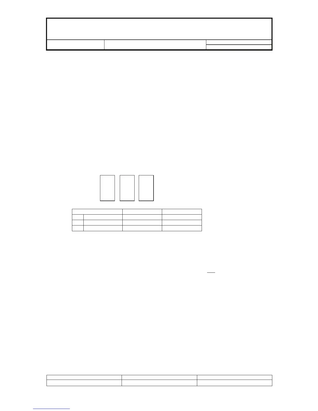
3. CRYSTAL SELECT
3.1 X202 crystal is marked with red, blue, and no color marking. Matching capacitors C223, C223A, and
C223B that are in PCB will be determined by the markings and are as follows:
C223B
C223A
C223
Crystal C223A C223B
A Red
Connect Connect
B NO COLOR
Connect NC
C Blue
NC NC
4. VCO ADJUSTMENT
4.1 Set the unit at PMR Ch1 (446.00625MHz) and connect a digital voltmeter to TP1 (VCO PD).
4.2 Press the PTT Button so the unit is in transmit mode.
4.3 Adjust L303 until the voltmeter reads around 3.1~3.2Vdc (without VCO Plate). L303 is located
under the shieldcan.
Solder VCO Plate and let temperature stabilize. Recheck TX VCO at Ch1
, should be 2.8~3.1Vdc
4.4 Release the PTT switch so the unit will be in Receive mode.
4.5 Observe the voltage at TP1, the voltage should be 2.5~3.2Vdc.
4.6 Set the unit at PMR Ch8 (446.09375MHz).
4.7 Press the PTT switch so the unit is in transmit mode.
4.8 Observe the voltage at TP1, the voltage should be 2.8~3.2Vdc.
4.9 Release the PTT switch so the unit will be in receive mode.
4.10 Observe the voltage at TP1, the voltage should be 2.5~3.2Vdc.
4.11 Set the unit at LPD Ch1 (433.075MHz)
4.12 Press the PTT switch so the unit is in transmit mode.
4.13 Observe the voltage at TP1, the voltage should be 1.0 ~ 1.8Vdc.
4.14 Release the PTT switch so the unit will be in receive mode.
4.15 Observe the voltage at TP1, the voltage should be 0.9 ~ 1.7Vdc.
NOTE : Above Specifications are measured with VCO Plate soldered.
Created by: Approved by: Rev. No:
For Stage : Release Date : Page 13 of 49
 Loading...