MUL TIBUS® I AND
80386
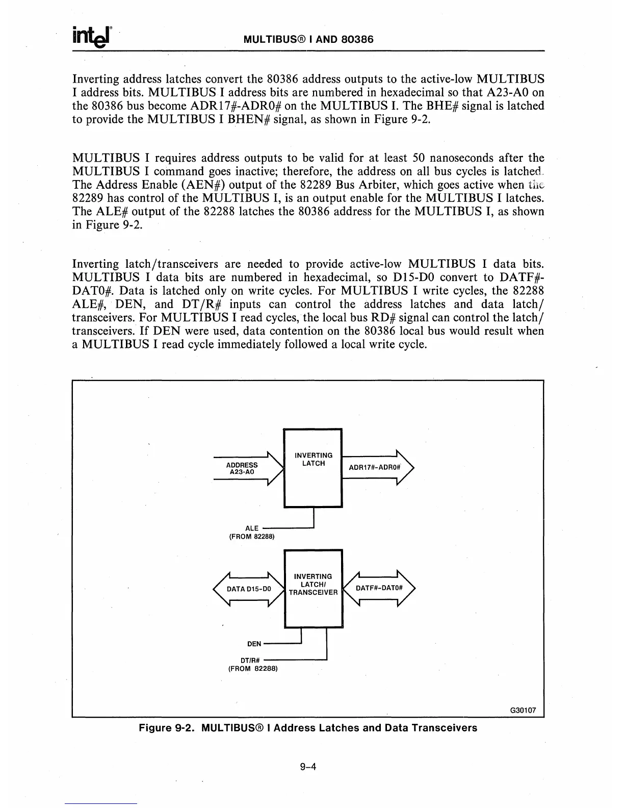
Inverting address latches convert the 80386 address outputs to the active-low MULTIBUS
I address bits.
MUL
TIBUS I address bits are numbered
in
hexadecimal
so
that
A23-AO
on
the 80386 bus become ADRl7#-ADRO#
on
the MULTIBUS I. The BHE# signal
is
latched
to provide the
MULTI
BUS I BHEN# signal, as shown
in
Figure 9-2.
MUL
TIBUS I requires address outputs to be valid for at least
50
nanoseconds after the
MULTI BUS I command goes inactive; therefore, the address
on
all bus cycles
is
latched.
The Address Enable (AEN#) output of the 82289 Bus Arbiter, which goes active when tll"
82289 has control of the
MUL
TIBUS I,
is
an output enable for the
MUL
TIBUS I latches.
The ALE# output of the 82288 latches the 80386 address for the MULTIBUS I, as shown
in
Figure 9-2.
Inverting latch/transceivers are needed to provide active-low MULTIBUS I data bits.
MULTIBUS I data bits are numbered
in
hexadecimal,
so
DI5-DO convert to DATF#-
DATO#.
Data
is
latched only
on
write cycles. For MULTIBUS I write cycles, the 82288
ALE#, DEN, and DT
/R#
inputs can control the address latches and data
latch/
transceivers. For MULTI BUS I read cycles, the local bus RD# signal can control the
latch/
transceivers.
If
DEN
were used, data contention
on
the 80386 local bus would result when
a MUL TIBUS I read cycle immediately followed a local write cycle.
ADDRESS
A23·AO
INVERTING
LATCH
ALE-----'
(FROM 82288)
INVERTING
LATCHI
TRANSCEIVER
DEN--
.....
DT/R#----....I
(FROM 82288)
ADR17#-ADRO#·
Figure
9-2. MUL TIBUS® I
Address
Latches
and Data
Transceivers
9-4
G30107