PHYSICAL DESIGN AND DEBUGGING
SOURCE
G30107
Figure 11-5. Series Termination
sv
G30107
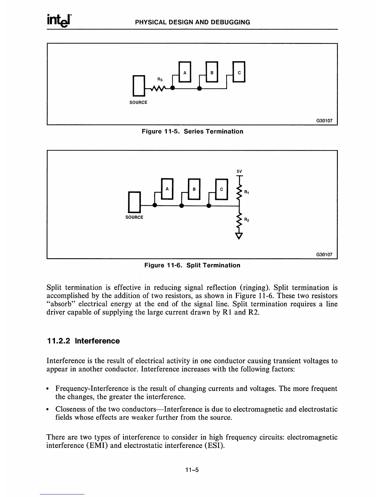
Figure 11-6. Split Termination
Split termination
is
effective in reducing signal reflection (ringing). Split termination
is
accomplished by the addition of
two
resistors,
as
shown
in
Figure 11-6. These two resistors
"absorb" electrical energy
at
the end of the signal line. Split termination requires a line
driver capable of supplying the large current drawn by
R1
and R2.
11.2.2 Interference
Interference
is
the result of electrical activity in one conductor causing transient voltages to
appear in another conductor. Interference increases with the following factors:
• Frequency-Interference
is
the result of changing currents and voltages. The more frequent
the changes, the greater the interference.
• Closeness of the two conductors-Interference
is
due to electromagnetic and electrostatic
fields whose effects are weaker further from the source.
There are two types of interference to consider in high frequency circuits: electromagnetic
interference
(EMI)
and electrostatic interference (ESI).
11-5