8XC196KC/8XC196KC20
PIN DESCRIPTIONS (Continued)
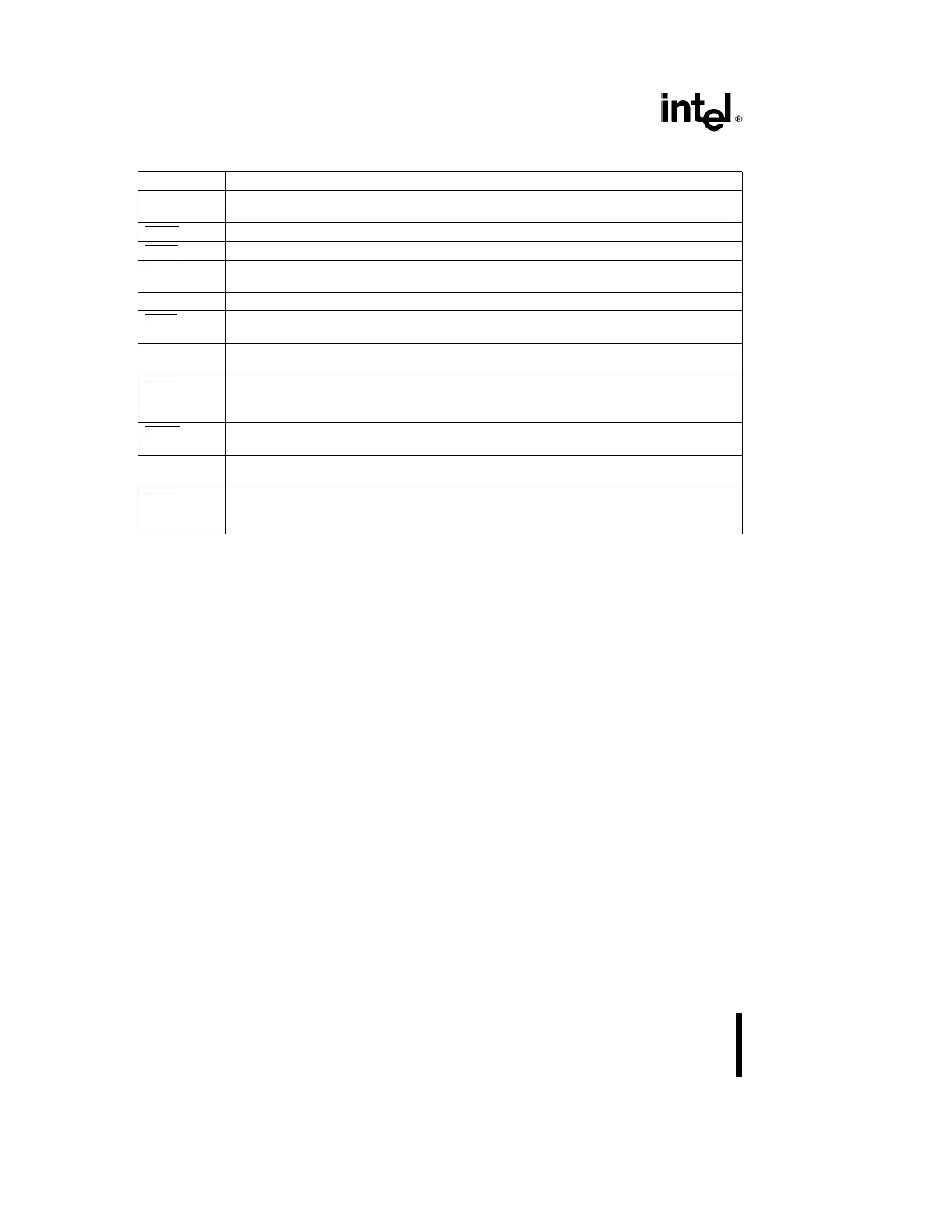
Symbol Name and Function
Ports 3 and 4 8-bit bidirectional I/O ports with open drain outputs. These pins are shared with the
multiplexed address/data bus which has strong internal pullups.
HOLD Bus Hold input requesting control of the bus.
HLDA Bus Hold acknowledge output indicating release of the bus.
BREQ Bus Request output activated when the bus controller has a pending external memory
cycle.
PMODE Determines the EPROM programming mode.
PACT A low signal in Auto Programming mode indicates that programming is in process. A high
signal indicates programming is complete.
CPVER Cummulative Program Output Verification. Pin is high if all locations have programmed
correctly since entering a programming mode.
PALE A falling edge in Slave Programming Mode and Auto Configuration Byte Programming Mode
indicates that ports 3 and 4 contain valid programming address/command information
(input to slave).
PROG A falling edge in Slave Programming Mode indicates that ports 3 and 4 contain valid
programming data (input to slave).
PVER A high signal in Slave Programmig Mode and Auto Configuration Byte Programming Mode
indicates the byte programmed correctly.
AINC Auto Increment. Active low input signal indicates that the auto increment mode is enabled.
Auto Increment will allow reading or writing of sequential EPROM locations without address
transactions across the PBUS for each read or write.
8
 Loading...
