Contents
vii
Figures
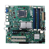
1. Intel Desktop Board D201GLY Components....................................................... 11
2. Back Panel Audio Connectors ..........................................................................15
3. LAN Connector LEDs ......................................................................................16
4. Location of the Standby Power Indicator........................................................... 19
5. Installing the I/O Shield .................................................................................23
6. Desktop Board D201GLY Mounting Screw Holes................................................. 24
7. Use DDR DIMMs ............................................................................................25
8. Installing a DIMM ..........................................................................................26
9. Connecting the IDE Cable ............................................................................... 28
10. Internal Headers ...........................................................................................29
11. Location of the Chassis Fan Header.................................................................. 32
12. Connecting a 2 x 10 or 2 x 12 Power Supply Cable ............................................33
13. Desktop Board Jumpers.................................................................................. 34
14. Removing the Battery ....................................................................................41
Tables
1. Feature Summary............................................................................................9
2. Desktop Boards D201GLY Components............................................................. 12
3. RJ-45 10/100 Ethernet LAN Connector LEDs .....................................................16
4. Front Panel Audio Header Signal Names ...........................................................30
5. Hi-Speed USB 2.0 Header Signal Names........................................................... 31
6. Front Panel Header Signal Names ....................................................................31
7. Front Panel Audio Header/Jumper Block ...........................................................35
8. Jumper Settings for the BIOS Setup Program Modes .......................................... 35
9. Front-panel Power LED Blink Codes..................................................................45
10. BIOS Error Messages ..................................................................................... 45
11. Safety Regulations......................................................................................... 47
12. Lead-Free Board Markings ..............................................................................52
13. EMC Regulations............................................................................................ 53
14. Product Certification Markings .........................................................................55
 Loading...