Contents
vii
Figures
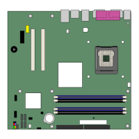
1. Intel Desktop Board D915GVWB Components .............................................................. 11
2. Location of Standby Power Indicator.............................................................................. 20
3. Installing the I/O Shield................................................................................................... 26
4. Mounting Screw Hole Locations ..................................................................................... 27
5. Lift Socket Lever............................................................................................................. 28
6. Lift the Load Plate and Don’t Touch the Socket Contacts .............................................. 28
7. Remove the Protective Socket Cover............................................................................. 29
8. Remove the Processor from the Protective Processor Cover/Do Not Touch................. 29
9. Install Processor.............................................................................................................30
10. Close the Load Plate ...................................................................................................... 30
11. Connecting the Processor Fan Heat Sink Cable to the Processor Fan Connector ........ 31
12. Dual Configuration Example 1........................................................................................ 32
13. Dual Configuration Example 2........................................................................................ 33
14. Dual Configuration Example 3........................................................................................ 33
15. Installing a DIMM............................................................................................................ 34
16. Connecting the IDE Cable .............................................................................................. 36
17. Connecting the Serial ATA Cable................................................................................... 37
18. Internal Headers............................................................................................................. 38
19. Back Panel Audio Connectors for Flexible 6-Channel Audio System ............................ 40
20. Location of Fan Headers ................................................................................................ 41
21. Connecting 2x10 Power Supply Cables ......................................................................... 42
22. Connecting 2x12 Power Supply Cables ......................................................................... 43
23. Location of Other Connectors......................................................................................... 44
24. Location of the BIOS Configuration Jumper Block ......................................................... 45
25. Back Panel Connectors.................................................................................................. 47
26. Removing the Battery ..................................................................................................... 52
27. F2 Key ............................................................................................................................53
Tables
1. Feature Summary............................................................................................................. 9
2. Manufacturing Option ..................................................................................................... 10
3. Desktop Board D915GVWB Components...................................................................... 12
4. RJ-45 10/100 Ethernet LAN Connector LEDs ................................................................ 16
5. USB 2.0 Header Signal Names ...................................................................................... 39
6. Front Panel Header Signal Names................................................................................. 39
7. Front Panel Audio Header Signal Names....................................................................... 39
8. Jumper Settings for the BIOS Setup Program Modes.................................................... 45
9. BIOS Beep Code ............................................................................................................ 57
10. BIOS Error Messages..................................................................................................... 57
11. Safety Regulations .........................................................................................................59
12. EMC Regulations............................................................................................................ 61
13. Product Certification Markings........................................................................................ 63