Installing and Replacing Desktop Board Components
45
Front Panel Audio Header
The front panel audio header shown in Figure 20, A supports both Intel High Definition
(HD) Audio and AC ’97 Audio.
Table 5 shows the pin assignments and signal names for
HD Audio and Table 6 shows
the pin assignments and signal names for AC ’97 Audio.
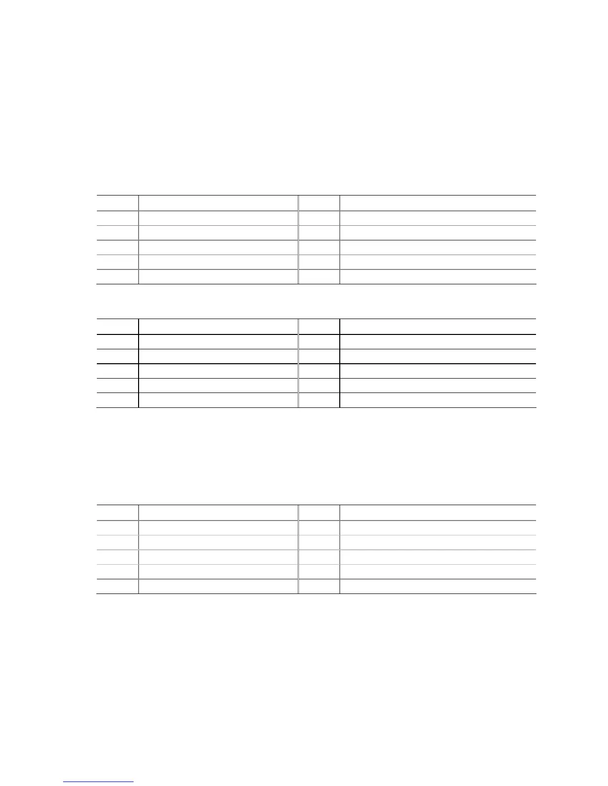
Table 5. Front Panel Audio Signal Names for Intel HD Audio
Pin Signal Name Pin Signal Name
1 PORT 1L (Microphone) 2 GND
3 PORT 1R (Microphone) 4 PRESENCE#
5 PORT 2R (Headphone) 6 SENSE1_RETURN
7 SENSE_SEND 8 KEY (no pin)
9 PORT 2L (Headphone) 10 SENSE2_RETURN
Table 6. Front Panel Audio Header Signal Names for AC ’97 Audio
Pin Signal Name Pin Signal Name
1 MIC 2 AUD_GND
3 MIC_BIAS 4 PRESENCE#
5 FP_OUT_R 6 AUD_GND
7 No connect 8 KEY (no pin)
9 FP_OUT_L 10 AUD_GND
IEEE 1394a Header
See Figure 20, B for the location of the IEEE 1394a header. Table 7 shows the pin
assignments for the header.
Table 7. IEEE 1394a Header Signal Names
Pin Signal Name Pin Signal Name
1 TPA1+ 2 TPA1-
3 Ground 4 Ground
5 TPA2+ 6 TPA2-
7 +12 V 8 +12 V
9 Key (no pin) 10 Ground
Chassis Intrusion Header
Figure 20, C shows the location of the chassis intrusion header. This header can be
connected to a mechanical switch on the chassis to detect if the chassis cover is
removed. This switch should be in the open position when the chassis cover is
installed and closed when the cover is removed.