1485 Jacobs Rd.
Deland, FL 32724
386.738.7307
P/N 53-00549-100 Rev. C 032619
www.intellitec.com
Intellitec
SERVICE MANUAL
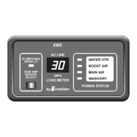
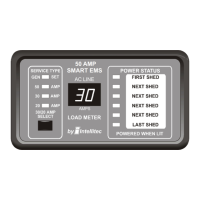
SMART EMS
TM
The replacement circuit breakers must be of the same type and rating.
FUSE
PLUGS - PINS & FUNCTIONS
F1
J1
J3
J4
J5
- 3 Amp ATO type, for EMS circuitry only. DO NOT replace with a fuse of higher rating. This could result in severe
damage to the circuitry or create a possible fire hazard.
- 2 pin plug used for High Pot Test Only. When shorted together, will operate EMS relays without the presence of
120 VAC.
- 4 pin Molex KK .156 - Display Panel Connector Mating Housing Molex 09-50-3041
1 Power
2 Data
3 Ground
4 Select Line
- 8 pin in-line Mate-N-Lock Mating housing AMP 640586-1
1 + 12 Volts
2 Ground
3 Relay 4 Normally Open
4 Relay 4 Common
5 Relay 4 Normally Closed
6 Relay 5 Normally Open
7 Relay 5 Common
8 Relay 5 Normally Closed
- 7 terminal block - Will accept up to 12 GA or 14 GA copper wire ONLY.
1 Neutral
2 From Circuit Breaker 3
3 Output of Relay 3
4 From Circuit Breaker 2
5 Output of Relay 2
6 From Circuit Breaker 1
7 Output of Relay 1
Pin Function
Pin Function
Terminal Function