EasyManua.ls Logo

Intellitec 50 Amp Smart EMS 900 - User Manual

Intellitec 50 Amp Smart EMS 900
16 pages
To Next Page IconTo Next Page
Loading...
131 Eisenhower Lane North
Lombard, IL 60148
630.268.0010 / 1.800.251.2408
P/N 53-00684-200 Rev. A 071301
www.Intellitecsve.com
Intellitec
INSTALLATION & SERVICE MANUAL
TM
50 AMP Smart Energy Management System Model 900
50 AMP
SMART EMS
50 Amp EMS Display Panel
P/N 00-00684-000
22 33 44 55 6
DANGER: HAZARD OF ELECTRICAL SHOCK OR BURN. TURN OFF POWER SUPPLY ON THIS EQUIPMENT BEFORE WORKING INSIDE.
LINE 2LINE 1
SMARTENERGYMANAGEMENTSYSTEM
ENCLOSED ENERGY MANAGEMENT EQUIPMENT
MODEL900
50 AMP SERVICE
by
MADE IN THE U.S.A.
Intellitec
6 M
A
I
N
M
A
I
N
11
4L54
R
LISTED
USC
50 Amp EMS Distribution Panel
P/N 00-00767-000
CAUTION
TM
The 50 AMP SMART EMS Model 900 is a centralized power switching, fusing and distribuition center.
Power from the 120/240 volt power source is fed into the box. The potential of lethal electrical shock is
present in this box. Inadvertent shorts at this box could result in damage and/or injury. All servicing of
this box should be done only by a qualified Service Technician
Diagnostic tools required: Low current Test Light, Accurate Voltmeter (digital readout preferred)
Clamp-on AC ammeter.
Question and Answer IconNeed help?

Do you have a question about the Intellitec 50 Amp Smart EMS 900 and is the answer not in the manual?

Intellitec 50 Amp Smart EMS 900 Specifications

General IconGeneral
BrandIntellitec
Model50 Amp Smart EMS 900
CategoryControl Systems
LanguageEnglish

Summary

Product Overview

System Components

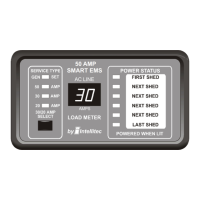
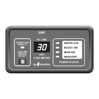
Describes the Display Panel, Distribution Panel, and Circuit Breakers.

Energy Management Functionality

Details the automatic sensing and control of power sources and loads.

System Operation

How the EMS Manages Power

Explains circuit protection, energy management, and controlled load operation.

Vehicle Power Source Operation

Covers startup, delays, power source detection, and load shedding logic.

Installation and Configuration

Display Panel Installation

Guidance on mounting and connecting the remote display panel.

Control Module Configuration

Details jumper settings for load shedding order and generator type.

Distribution Panel Installation

Instructions for mounting the distribution panel and installing breakers.

Wiring and Connections

Specifics on connecting loads, power sources, and control module terminals.

Low Voltage Control Wiring

Explains wiring for thermostats and air conditioner compressors/fans.

Control Module Connector Details

Detailed pinout and function for all EMS control module connectors.

Testing Procedures

Performance and Hi-POT Testing

Tests for system readiness, insulation integrity, and shorts.

System Test for Operation

Tests power application, relay operation, and load shedding functionality.

Trouble Shooting Guide

No Power or Appliance Issues

Diagnosing no 120V appliances, partial operation, or breaker trips.

Air Conditioner and Shedding Problems

Resolving AC issues and incorrect load shedding order.

Remote Display Errors

Diagnosing display errors, incorrect source indications, or strange characters.

Related product manuals